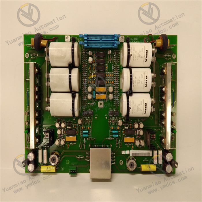
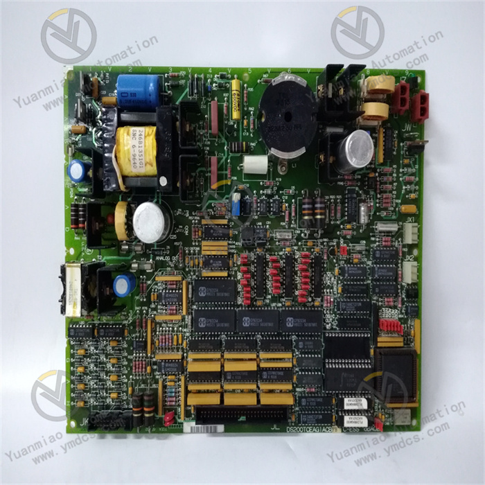
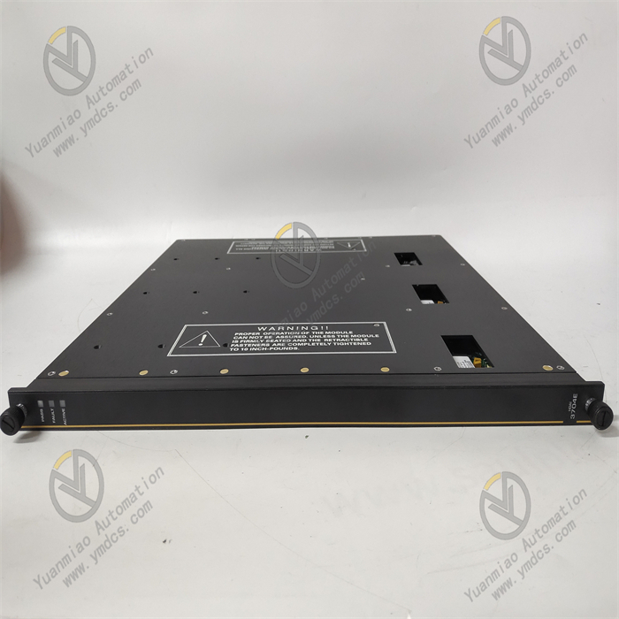
Description
GE 8913-PS-AC
As an AC-input DC-output switching power supply module, the GE 8913-PS-AC is primarily designed to provide high-precision and high-stability DC power for industrial automation equipment such as PLCs, I/O modules, sensors, and actuators. Leveraging its wide input voltage range, multiple protection mechanisms, and robust environmental adaptability, it is widely used in Distributed Control Systems (DCS), Programmable Logic Controller (PLC) systems, and standalone automated equipment across industries including electric power, chemical engineering, intelligent manufacturing, and metallurgy. It serves as a critical core component in the power supply chain of industrial control systems.
1. Technical Parameters
Input Parameters: Supports a wide AC input voltage range of 85V~265V, compatible with grid voltages in different regions worldwide; input frequency range is 47Hz~63Hz, adaptable to grid frequency fluctuations; input current is ≤5A (at AC 85V), with input surge suppression function, and surge current is ≤30A/20ms.
Output Parameters: Output voltage is DC 24V, with a voltage regulation accuracy of ±0.5% and a load regulation rate of ±1% (load range: 10%~100%); rated output current is 20A, and maximum output power is 480W; output ripple and noise are ≤100mVp-p (20MHz bandwidth), ensuring pure power supply.
Protection Parameters: Equipped with multiple protection functions including Overcurrent Protection (OCP), Overvoltage Protection (OVP), Undervoltage Protection (UVP), Overtemperature Protection (OTP), and Short-Circuit Protection (SCP); the overcurrent protection threshold is 110%~150% of the rated current, with automatic recovery; the overtemperature protection threshold is 85℃±5℃, and the module automatically reduces output power at high temperatures.
- Environmental Adaptability Parameters: Operating temperature ranges from -20℃ to 70℃, and storage temperature ranges from -40℃ to 85℃; relative humidity is 5%~95% (no condensation); electromagnetic interference resistance complies with IEC 61000-4-2 (ESD), IEC 61000-4-3 (radiated immunity), and IEC 61000-4-4 (electrical fast transient/burst) standards; protection rating is IP20 (module itself), supporting DIN rail mounting or wall-mounted installation.
- Physical and Efficiency Parameters: Dimensions are 200mm×120mm×80mm, and weight is ≤1.5kg; conversion efficiency is ≥92% (under rated load), and power factor is ≥0.95 (at AC 220V/rated load); Mean Time Between Failures (MTBF) is ≥100,000 hours, meeting industrial-grade high-reliability requirements.
2. Functional Features
Wide Voltage Input and High-Precision Output for Complex Grid Environments: The AC 85V~265V wide input voltage design can handle scenarios such as grid voltage fluctuations in industrial sites, low-voltage power supply, or unstable power supply in remote areas; the DC 24V output voltage has a regulation accuracy of ±0.5% and a load regulation rate of only ±1%. Even when the load changes frequently (e.g., motor start-stop), the output voltage fluctuation is controlled within a very small range, providing pure and stable power for precision electronic equipment (such as PLCs and sensors).
Multiple Intelligent Protection for System Safety: Integrates comprehensive protection functions including overcurrent, overvoltage, short-circuit, and overtemperature protection. When abnormal working conditions (such as output short-circuit or excessive load) are detected, it can respond quickly within 100μs to protect the power module and downstream equipment by means of current limiting, output shutdown, or derated operation; after faults such as overcurrent and undervoltage are resolved, the module can automatically resume output without manual intervention, improving system operation and maintenance efficiency.
High Conversion Efficiency and Energy-Saving Design for Reduced Operating Costs: The conversion efficiency under rated load is ≥92%, much higher than that of traditional linear power supplies (efficiency of approximately 60%~70%), effectively reducing power loss; the power factor is ≥0.95, reducing harmonic pollution to the power grid and meeting the requirements of green industrial development; the intelligent heat dissipation design with a built-in temperature-controlled fan that only starts when the load is ≥50% or the temperature is ≥50℃, balancing heat dissipation effect and energy-saving needs.
Industrial-Grade Reliability and Environmental Adaptability for Severe Scenarios: Uses wide-temperature industrial-grade components that have undergone multiple rigorous tests including high-low temperature cycles, vibration and impact, and electromagnetic interference; the internal independent shielding design can resist electromagnetic radiation from strong interference sources such as frequency converters and motors in industrial sites, ensuring stable operation in harsh environments with high temperature, high humidity, and heavy dust; the MTBF exceeds 100,000 hours, meeting the high-reliability requirements of critical industrial scenarios.
- Convenient Monitoring and Expansion for Enhanced O&M Flexibility: Equipped with a power indicator (PWR), fault indicator (FAULT), and output indicator (OUT) for intuitive display of the module's operating status; supports parallel redundant operation, and multiple modules in parallel can achieve superimposed output current while having current sharing function with a current sharing error of ≤5%, meeting high-load power supply needs; some models support RS485 communication interface, which can upload parameters such as output voltage, current, and temperature via Modbus protocol to achieve remote monitoring and fault diagnosis.
3. Working Principle
Input Rectification and Filtering Stage: The AC input voltage (AC 85V~265V) first passes through an EMC (Electromagnetic Compatibility) filter circuit to remove high-frequency interference and noise from the power grid; then enters the rectifier bridge to convert AC to pulsating DC; finally, it is filtered through a large-capacity electrolytic capacitor to obtain smooth high-voltage DC (approximately 300V DC), providing stable input for the subsequent switching conversion stage.
High-Frequency Switching Conversion Stage: The high-voltage DC enters the power conversion circuit, where a PWM (Pulse Width Modulation) controller drives power switches (such as MOSFETs) to turn on and off at high speed, converting the high-voltage DC into high-frequency pulsed AC (frequency is usually 50kHz~200kHz). The PWM controller dynamically adjusts the pulse width by real-time detecting the output voltage and current, thereby accurately controlling the output energy and ensuring the stability of the output voltage.
Voltage Reduction and Rectification Filtering Stage: The high-frequency pulsed AC is stepped down by a high-frequency transformer and converted into low-voltage high-frequency AC that meets the output requirements; then it is rectified through a fast recovery diode or synchronous rectification circuit to convert the low-voltage AC into pulsating low-voltage DC; finally, it is further filtered through an LC filter circuit (inductor + capacitor) to remove pulsating components, obtaining a stable DC 24V output voltage with minimal ripple for downstream industrial equipment.
- Feedback and Protection Stage: The output voltage and current signals are fed back to the PWM controller in real-time through a sampling resistor. The controller compares the sampled value with the reference value and corrects the output voltage by adjusting the pulse width to form closed-loop control; at the same time, the protection circuit monitors parameters such as input voltage, output current, and module temperature in real-time. When an abnormality is detected (such as output short-circuit or excessive temperature), it immediately sends a signal to the PWM controller to control the power switch to turn off or limit current, realizing the protection function.
4. Common Faults and Solutions
- Fault 1: No output from the power module, all indicators not lit
- Possible Causes: Input power failure, loose or oxidized input wiring, burned internal fuse of the power module, failure of the internal core circuit of the module.
- Solutions: ① Use a multimeter to detect the AC input voltage and confirm it is within the range of AC 85V~265V; ② Check the input terminals, remove the wiring, polish the terminals with sandpaper to remove oxide layers, and re-tighten the wiring; ③ Open the module housing (after power-off) and check the internal fuse; if burned, replace it with a fuse of the same specification (replacement should be done only after confirming no short-circuit fault); ④ If there is still no output after replacing the fuse, determine that the internal circuit of the module is faulty, and contact after-sales service for repair or replace the module.
- Fault 2: Low output voltage, load unable to work normally
- Possible Causes: Low input voltage, excessive load exceeding rated current, excessive voltage drop due to loose output wiring, failure of the internal feedback circuit of the module.
- Solutions: ① Detect the AC input voltage; if it is lower than AC 85V, install a voltage stabilizer or improve the power supply line; ② Calculate the total load current; if it exceeds the rated output current (20A) of the module, reduce the load or add parallel modules; ③ Check the output wiring to ensure it is firm, and replace with thicker output wires to reduce line voltage drop; ④ If the above measures are ineffective, use professional equipment to detect the module's feedback circuit; if faulty, repair or replace the module.
- Fault 3: Fault indicator (FAULT) stays on, module has no output or derated output
- Possible Causes: Output short-circuit, overcurrent load, module overtemperature, abnormal input voltage (overvoltage/undervoltage).
- Solutions: ① Disconnect all output loads and restart the module; if the fault indicator goes out, it indicates a load short-circuit or overcurrent; connect the loads one by one to identify and repair the faulty equipment; ② If the fault indicator remains on after disconnecting the loads, check if the input voltage is within the normal range and eliminate input overvoltage/undervoltage issues; ③ Check the module's heat dissipation environment; if the temperature inside the cabinet is too high, install a cooling fan or clean the dust on the module surface to ensure smooth ventilation; ④ If the above measures are ineffective, determine that the internal protection circuit of the module is faulty, and contact after-sales service for handling.
- Fault 4: Excessive output ripple causing data fluctuations in downstream equipment (e.g., sensors)
- Possible Causes: Aging of output filter capacitors, unstable load (e.g., frequently starting and stopping motors), poor module grounding, severe interference from the input power grid.
- Solutions: ① After power-off, check the internal output filter capacitors of the module; if bulging or leaking occurs, replace them with capacitors of the same specification; ② Connect absorption capacitors in parallel across the terminals of frequently starting and stopping loads to reduce load interference on the power supply; ③ Ensure the module's grounding terminal is reliably grounded with a grounding resistance of ≤4Ω; ④ Install a power filter at the module's input terminal to filter out high-frequency interference from the power grid.
- Fault 5: Module shuts down automatically during operation, can recover after cooling
- Possible Causes: Module overtemperature protection, cooling fan failure, long-term overload of the load.
- Solutions: ① Check the module's cooling fan; if the fan does not rotate or rotates too slowly, replace the fan; ② Calculate the load current; if it exceeds the rated value for a long time, add parallel modules or optimize load distribution; ③ Improve the module's installation environment, ensure there is no obstruction around the module, and the cabinet has good ventilation; if necessary, install a forced heat dissipation device.
- Fault 6: Uneven current sharing among modules during parallel operation, some modules overloaded
- Possible Causes: Inconsistent models of parallel modules, poor connection of current-sharing wires, excessive output voltage deviation among modules.
- Solutions: ① Ensure all parallel modules have identical models and specifications; ② Check the connection of current-sharing wires to ensure they are firm and have good contact; ③ Use a multimeter to detect the output voltage of each module; if the deviation exceeds ±0.5V, calibrate the output voltage using the voltage adjustment potentiometer (if available) on the module to ensure consistency.