Description
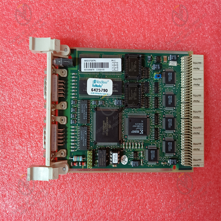
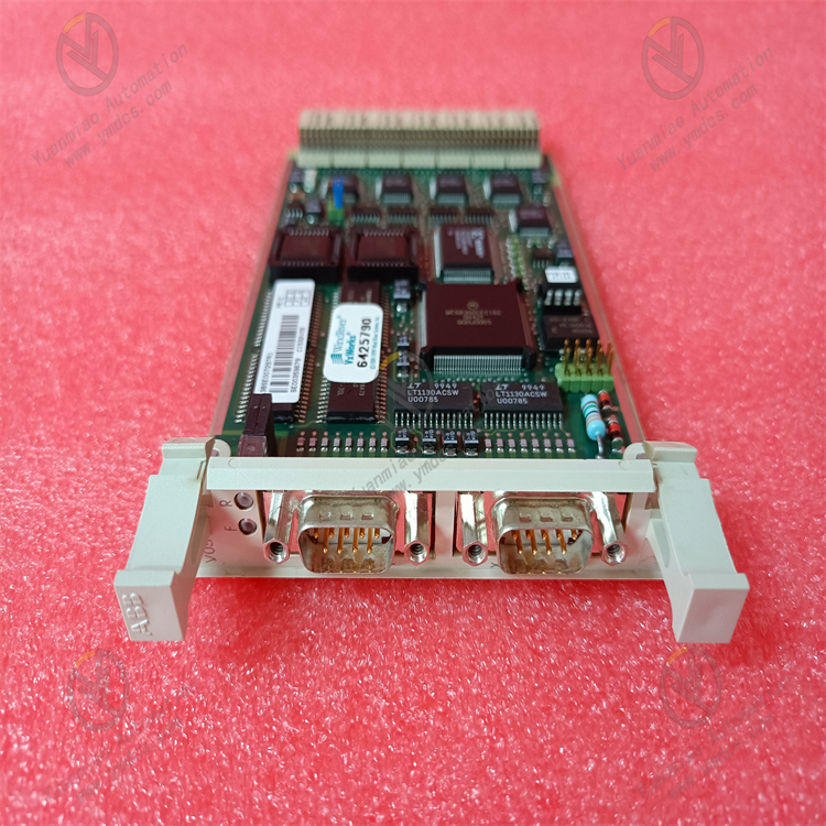
ABB CI532V05 3BSE007297R1
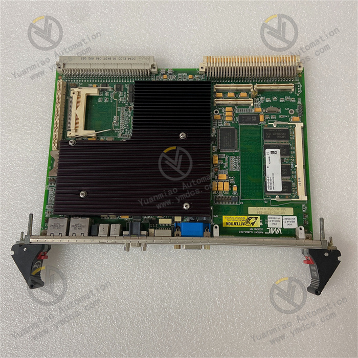
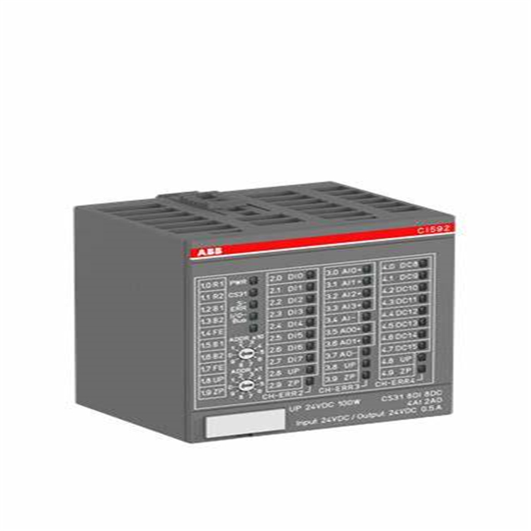
ABB CI532V05 3BSE007297R1 is a universal sub-module interface.
Features and Applications
High Reliability: Manufactured with high-quality materials and advanced production processes, it offers high stability and reliability, capable of operating steadily in harsh industrial environments.
Strong Versatility: Suitable for communication and data transmission between various industrial automation devices, facilitating system expansion and upgrades for users.
Efficient Data Processing: Supports multiple communication protocols and data formats, enabling efficient data transmission and processing, and can communicate with various industrial automation devices.
Safety Protection Functions: Equipped with safety protections such as overload protection and short-circuit protection, which can effectively prevent equipment and personnel from harm caused by abnormal situations, as well as safeguard against unauthorized access and data leakage.
Technical Parameters
- Dimensions: Approximately 10.2cm × 7.6cm × 12.7cm.
- Weight: 0.165 kg.
- Operating Voltage: 210V.
- Communication Protocols: Supports Profibus DP-V1 protocol.
- Number of Channels: 2.
- Transmission Speed: 9.6 - 12000 kbit/s.
- Line Redundancy: Supported.
- Module Redundancy: Supported.
- Hot Swapping: Supported.
- Maximum Units on CEX Bus: 12.
- Connector: DB female (9-pin).
- Typical 24V Power Consumption: 190 mA.
- Operating Temperature: 55°C.
Fault Troubleshooting Guide
1. Gather Fault Information: Clarify fault manifestations, such as error messages, indicator light status, abnormal data transmission, and the scenario in which the fault occurred.
2. Check Hardware Connections: Inspect power supply, communication, and signal I/O lines to ensure secure connections without looseness, damage, or short circuits. Measure whether the power output voltage is normal.
3. Inspect Module Status Indicators: Refer to the technical manual to analyze fault information reflected by the on/off and flashing states of the indicators.
4. Verify Communication Settings: Confirm that communication protocol configurations (e.g., baud rate, data bits, stop bits, parity) are consistent with other devices. Check network settings (e.g., IP address, port number) for correctness and conflicts.
5. Review Parameter Settings: Use programming software or configuration tools to check if the module’s parameter settings meet actual application requirements.
6. Investigate Electromagnetic Interference: Observe for interference sources (e.g., large motors) around the module. If present, take isolation or shielding measures, ensuring proper grounding of the shield layer.
7. Software Upgrade and Factory Reset: Check the firmware version and attempt an upgrade. If issues persist, restore factory settings after backing up important configuration information.
8. Replacement Testing: Test with a spare module or install the faulty module in another normal system to determine if the fault relates to the original system’s equipment or environment.
Installation Guide for ABB CI532V05 3BSE007297R1 Communication Interface Module
1. Pre-Installation Preparation
1. Confirm Product and Accessories
- Module Model: CI532V05 (3BSE007297R1), belonging to ABB AC 800M series communication modules, supporting Modbus RTU and other protocols.
- Accessory Check: Ensure accessories include mounting rails, screws, communication cables, power adapters (if applicable), etc.
- Environmental Requirements:
- Temperature: -20°C ~ +60°C (operating), -40°C ~ +85°C (storage).
- Humidity: 5% ~ 95% (non-condensing).
- Protection Level: IP20 (must be installed in a control cabinet to avoid dust and liquid intrusion).
2. Tool Preparation
- Screwdrivers (usually Phillips or flathead), wire strippers, multimeter.
- Programming equipment: Laptop + ABB Control Builder M software (for parameter configuration).
- Anti-static wrist strap (to prevent electrostatic damage to electronic components).
2. Installation Steps
1. Mount the Module on the Rail
- Rail Type: Standard DIN rail (35mm wide), compatible with most industrial control cabinets.
- Procedure:
- Align the rail clips on the module’s back with the rail, and press the module downward until the clips snap onto the rail.
- Secure the module with screws through the mounting holes on both sides (if the rail supports screw fixation) to ensure the module is stable and does not wobble.
2. Power Connection
- Voltage Specification: DC 24V (typical value, subject to the manual), with correct polarity (+/- terminals).
- Wiring Steps:
- Locate the power terminals on the module (usually labeled 24V+ and GND).
- Strip the power cable ends with a wire stripper (strip length: ~5-8mm), ensuring no burrs on the conductors.
- Insert the power cables into the terminals and tighten the screws to avoid poor contact.
- Use a multimeter to measure the input voltage, ensuring it stabilizes within the rated range (e.g., 24V±10%).
3. Communication Line Connection
- Supported Protocols: Modbus RTU (RS485), may need to be configured as Slave mode.
- Wiring Diagram:
Terminal Label Function Connection Instructions RS485_A Positive communication (A wire) Connect to RS485_A of the master or slave RS485_B Negative communication (B wire) Connect to RS485_B of the master or slave GND Signal ground Recommended to share ground with the system to reduce interference - Notes:
- Use shielded twisted-pair cables, with the shield grounded at one end (typically to the control cabinet’s metal shell).
- For multi-node networks, install a 120Ω termination resistor at the end node (the module may have a built-in resistor, enabled via a jumper cap).
4. Integration with the Control System
- Installation Location: It is recommended to install the module close to the controller (e.g., ABB PM866 processor module) or other communication modules to shorten communication cable lengths.
- Rail Layout: Follow the principle of "separating high voltage and low voltage," avoiding parallel routing of power cables and communication cables to reduce electromagnetic interference.

3. Parameter Configuration and Testing
1. Software Configuration (Taking Modbus RTU as an Example)
- Step 1: Connect Programming Equipment
Connect the laptop to the control system network via USB or Ethernet, and open the Control Builder M software. - Step 2: Add the Module
Scan for hardware devices in the software, locate the CI532V05 module, add it to the project, and assign a unique slave address (e.g., 1-247, must match the master). - Step 3: Configure Communication Parameters
- Baud Rate: Selectable (e.g., 9600, 19200, 38400) to match the master.
- Data Bits: 8 bits (default).
- Stop Bits: 1 or 2 bits (per the master’s settings).
- Parity: None, Odd, or Even.
- Step 4: Download Configuration
Download the parameters to the module and restart it for the configuration to take effect.
2. Function Testing
- Indicator Check:
- PWR (Power Light): Constant on indicates normal power supply.
- COM (Communication Light): Flashing indicates active communication; constant on or off may signal a communication fault.
- Data Transceive Test:
Use a master device (e.g., PLC) to send read/write commands, and verify whether data is correctly transmitted by reading data from slave devices (e.g., sensors) or controlling actuators via the module. - Troubleshooting:
If communication fails, check wiring polarity, slave address, and baud rate for matching. Alternatively, use a serial debugging tool (e.g., Modbus Poll) to test the module’s response directly.
4. Safety and Maintenance Recommendations
- Power-Off Operation: Always disconnect power before installing or removing the module to avoid component damage from live plugging/unplugging.
- ESD Protection: Wear an anti-static wrist strap when handling the module to avoid direct contact with circuit board terminals.
- Cable Management: Secure communication and power cables to prevent terminal loosening due to pulling.
- Regular Inspections: Quarterly checks of module indicator status, terminal tightness, and heat dissipation to ensure long-term stable operation.