Description
GE Multilin SR745-W3-P5-G5-HI
I. Overview
The GE Multilin SR745-W3-P5-G5-HI is a high-performance transformer management relay meticulously designed for various transformer systems, belonging to GE Multilin's 745 series. With its excellent design and advanced technology, it excels in transformer protection and precise control, providing comprehensive protection and monitoring for power transformers ranging from small to large. Widely applied in key fields such as power supply systems, industrial automation production lines, substation facilities, and energy production enterprises, it serves as a core device to ensure the safe, stable, and efficient operation of transformers, helping to enhance the reliability and stability of the entire power system.
II. Functional Features
Comprehensive Precision Protection Mechanism
The relay is equipped with rich and practical protection functions to safeguard transformer operation in all aspects:
- Overcurrent Protection continuously monitors current and acts swiftly once the current exceeds the set threshold, preventing transformer damage from overheating caused by excessive current.
- Overvoltage Protection effectively responds to abnormal voltage increases, promptly cutting off the circuit to avoid transformer insulation breakdown due to excessive voltage.
- Ground Fault Protection accurately identifies ground faults and responds rapidly to ensure the safety of personnel and equipment.
- Resonant Overvoltage Protection specifically addresses potential resonant overvoltage phenomena, providing early warnings and taking measures to prevent transformer damage from resonance.
- Undervoltage Protection acts promptly when voltage suddenly disappears, avoiding transformer operation under abnormal low voltage.
- Overload Protection constantly monitors transformer load conditions, issuing alarms and taking load reduction measures when the load is excessively high for a long time, preventing transformer damage from overheating. These protection functions collaborate to build an impregnable safety barrier for transformers.
High-Precision Parameter Measurement and Monitoring
It can accurately measure and monitor key parameters of transformer operation, such as current, voltage, power, frequency, etc. Additionally, it monitors related parameters such as individual harmonics and total harmonic distortion. The high-precision measurement data provides reliable and accurate information support for operation and maintenance personnel, enabling them to quickly and accurately assess the transformer's operational health, whether for real-time monitoring of the transformer's status or in the process of fault troubleshooting and in-depth analysis, and to promptly identify potential issues and take corresponding measures.
Intelligent Adaptive Regulation Function
It features advanced adaptive functions that can automatically adjust and optimize working parameters based on the actual operation status of the transformer. For example, it can dynamically correct CT ratio mismatch to ensure the accuracy of current measurement and protection; the adaptive time overcurrent element can intelligently adjust the action time of overcurrent protection according to load changes, improving the sensitivity and reliability of protection; the adaptive harmonic suppression function can effectively address complex and changeable harmonic issues in the power grid, reducing the impact of harmonics on the transformer and enhancing system stability. Through these adaptive functions, the reliability and stability of the transformer system are significantly improved, and equipment failure rates are reduced.
Convenient and Flexible Communication and Configuration
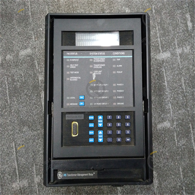
It supports multiple common communication protocols such as RS232, RS485, Ethernet, etc., and is perfectly compatible with mainstream communication specifications such as Modbus and Profibus, facilitating integration with various automation system architectures. With these communication interfaces, efficient remote data transmission, real-time monitoring of transformer operation status, and precise remote control can be achieved. Meanwhile, the relay provides a simulation test function, allowing users to simulate various fault conditions on a computer to test the relay's operation. Its 40-character backlit LCD display and input keyboard facilitate manual adjustment of set values, and it also supports EnerVista 745 setting software for more convenient setpoint management.
Exceptional Reliability and Durability
High-quality raw materials and advanced manufacturing processes are used in the product's manufacturing, endowing it with extremely high reliability and durability. Some models are specially optimized for harsh industrial environments, such as using sealed rubber strips for the housing to effectively prevent dust and ensure the cleanliness and reliability of internal components; they have good electromagnetic interference resistance and can operate stably in complex electromagnetic environments. Even in harsh industrial environments, they can always maintain stable operation, significantly reducing the probability of equipment failures and the input of overall maintenance costs.
III. Technical Parameters
Power Parameters
With excellent power adaptability, the control power input ranges from 90-300 VDC DC power and 70-265 VAC AC power, seamlessly adapting to the power supply requirements of different power systems to ensure the device's stable operation in various power environments. The operating frequency range is set at 48-62Hz, covering the power frequency standards of most regions worldwide, with broad geographical applicability.
Electrical Parameters
It provides multiple rated current specifications for flexible selection according to the transformer's load current in practical application scenarios, ensuring accurate acquisition and processing of current signals. The phase CT secondary coil is commonly configured in a specific specification, designed to accurately acquire current signals from each phase of the transformer, providing a reliable data foundation for internal protection algorithms and parameter calculations. The voltage input burden is less than 0.025 VA (at 120 V), ensuring low power consumption and stable operation under different voltage inputs. The source VT range is 2-600 kV / 60-120 V, adaptable to transformer applications of multiple voltage levels.
Interface Parameters
Equipped with 16 logic input ports, it can conveniently access various types of sensors and control signal sources to achieve comprehensive perception and reception of the transformer's operating environment and control commands; it has 8 output relays and 2 analog output ports with a standard output signal of 4-20mA, facilitating connection to external devices such as data acquisition modules and regulating actuators in automation control systems for remote signal transmission and precise control. It also has an RS232 program port for users to perform programming and configuration operations.
Other Parameters
The protection level of some models can reach a high standard, with good dustproof and water splash resistance, suitable for harsh industrial outdoor environments or dusty and humid indoor working environments. The operating temperature range is generally -40°C to +60°C, capable of adapting to temperature changes in most conventional and some extreme industrial environments. In terms of humidity, it can adapt to non-condensing environments with a relative humidity of up to 90%, ensuring stable operation in humid environments. The product's dimensions are reasonably designed for easy installation and arrangement in electrical control cabinets or equipment integration scenarios, and it weighs approximately 4.8kg. The moderate weight not only facilitates single-person installation, handling, and maintenance operations but also ensures stability after installation.
IV. Operation Guide
Local Operation
- Boot and Initialization Process: After the device is powered on, the SR745-W3-P5-G5-HI relay automatically starts the self-check and initialization program. At this time, the LED indicators on the front panel flash in a specific order to visually reflect the self-check progress; the 40-character LCD display simultaneously shows detailed self-check information, including hardware status detection results and software version information. After the self-check process is successfully completed, the LCD display automatically switches to the interface displaying the transformer's real-time operating parameters, such as the current three-phase current values and three-phase voltage values, to facilitate operators in mastering the transformer's operating status at the first time.
- Menu Operation Steps: If operators need to perform function settings, parameter adjustments, or information viewing on the device, they can press the eye-catching "Menu" button on the front panel, and the device will enter the main menu interface. The main menu interface is simple and clear, including main function options such as "Settings", "Monitoring", and "Fault Records". By pressing the up and down direction keys on the front panel, operators can quickly switch and select among the menu options, and pressing the "Enter" key after selecting the desired function option will enter the corresponding submenu.
- Parameter Setting Method: In the "Settings" submenu, it is further subdivided into special setting submenus such as "Transformer Parameters", "Protection Settings", and "Communication Settings". For example, in the "Transformer Parameters" submenu, operators can accurately set key parameters of the transformer such as rated power, rated current, and rated voltage according to the specification model of the actually connected transformer; in the "Protection Settings" submenu, important protection parameters such as the action current threshold and action time delay of the overcurrent protection function, and the action voltage threshold of the overvoltage protection function can be flexibly adjusted. When entering parameter values, use the specially equipped digital keys on the front panel for operation, and after input is completed, press the "Enter" key again, and the device will automatically save and confirm the set parameter values.
- Application of Monitoring Function: After entering the "Monitoring" menu, operators can view multiple operating parameters of the transformer in real time, including real-time values of three-phase current, three-phase voltage, current output power of the transformer, and operating frequency and other key information. At the same time, the menu interface intuitively displays the real-time operating status of the transformer, such as running, stopped, or fault alarm status, etc., to facilitate operators in mastering the transformer's working conditions at any time and timely discovering potential problems.
- Method for Viewing Fault Records: When a fault occurs during the transformer's operation, the SR745-W3-P5-G5-HI device automatically and timely records detailed fault information. Operators can view the specific type of fault, such as overcurrent fault, overvoltage fault, ground fault, etc.; the accurate time of the fault, accurate to the second; and the values of various operating parameters of the transformer at the moment of the fault, such as current, voltage, power, etc., by entering the "Fault Records" menu. These detailed fault record information provides crucial clues for subsequent fault troubleshooting and analysis, helping technicians quickly locate the cause of the fault and formulate effective solutions.
- Method for Exiting Operations: After operators complete all local operation tasks, they can press the "Exit" key on the front panel, and the device will gradually return to the upper-level menu interface. Continuously pressing the "Exit" key until completely exiting the menu operation interface and returning to the main interface displaying the transformer's real-time operating parameters, at which time the device continues to maintain real-time monitoring and protection of the transformer's operating status.
Remote Operation
- Establishment of Communication Connection: Before performing remote operations, it is essential to ensure that the communication line connection between the SR745-W3-P5-G5-HI device and the external automation system is accurate, and the communication parameter settings of both parties are completely consistent. Common communication connection methods include RS485 serial communication, Ethernet communication, etc. Taking RS485 communication as an example, it is necessary to carefully check whether the wiring polarity of the communication cable is correct to ensure a stable and reliable physical connection between the device and the automation system. At the same time, according to the actual connection situation, accurately set the corresponding communication parameters in the device's "Communication Settings" menu and the communication parameter configuration interface of the automation system, such as baud rate (which can be set according to actual needs, up to a specific value), communication address (used to uniquely identify the device's position in the communication network), etc.
- Operation Process of Monitoring Software: After completing the communication connection and parameter setting, operators open the host computer monitoring software. In the device management interface of the monitoring software, find the device icon corresponding to the SR745-W3-P5-G5-HI. The communication connection between the monitoring software and the device can be attempted by double-clicking the icon or by first selecting the device icon and then clicking the "Connect" button on the software interface. After the connection is successful, the monitoring software interface will display various operating parameters, status information, etc. of the transformer in real time, and the displayed content is basically the same as the information presented by the "Monitoring" function in the device's local operation interface, facilitating remote operators to understand the transformer's operation situation in real time.
- Operation of Remote Parameter Setting: The monitoring software is equipped with a parameter setting interface for the SR745-W3-P5-G5-HI device. In this interface, operators can perform remote setting operations on transformer parameters, protection parameters, communication parameters, etc. The operation method is similar to the device's local menu setting method. For example, when setting the transformer's rated current parameter, enter the accurate value in the corresponding parameter input box in the software interface, and then click the "Save" or "Apply" button to send the set parameter value to the device side. However, when performing remote parameter setting operations, it is necessary to attach great importance to the management of operation permissions. Only personnel with corresponding operation permissions can perform parameter modification operations to ensure the safety and accuracy of the entire system operation and avoid equipment failures or production accidents caused by misoperations.
- Key Points of Remote Control Operations: Some monitoring software with complete functions supports remote control operations on the transformer, such as remotely starting and stopping the transformer operation, etc. In the monitoring software interface, there is usually a special transformer control button area. Operators can click the corresponding control buttons, such as "Start" and "Stop" buttons, etc. The monitoring software will send the corresponding control commands to the SR745-W3-P5-G5-HI device according to the preset communication protocol. After the device receives the control commands, it will quickly execute the corresponding control actions to achieve remote control of the transformer. During remote control operations, operators must always pay attention to the actual operation status of on-site equipment and the safety of surrounding personnel to ensure the safety and reliability of remote control operations and prevent equipment damage or personal injury accidents caused by improper remote control.


