Description
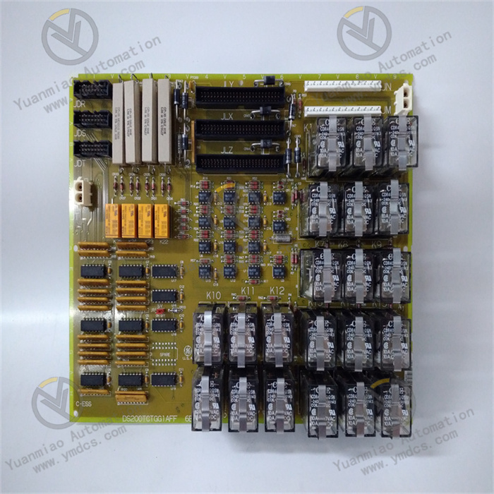
GE DS200TCQAG1BHF
GE DS200TCQAG1BHF is a core temperature control and signal conditioning module developed for the Mark VIe Distributed Control System (DCS). It belongs to the EX2100 series I/O module family and is primarily positioned as the "temperature monitoring and precise control hub" for large-scale power equipment such as industrial steam turbines, gas turbines, and boilers. Leveraging GE's dual technical expertise in industrial control and sensor signal processing, this module adopts a high-precision signal acquisition circuit, a multi-channel independent conditioning architecture, and an enhanced anti-interference design. It undertakes key tasks such as real-time acquisition, filtering conditioning, linearization processing of temperature signals, and control signal output for critical parts of large-scale power equipment (e.g., steam turbine bearings, gas turbine combustion chambers, boiler heating surfaces). Meanwhile, it is equipped with functions including signal abnormality diagnosis, channel fault alarm, and real-time communication with the system controller.
As a dedicated temperature control module for the Mark VIe control system, DS200TCQAG1BHF is highly compatible with the system's hardware architecture and software platform. It can be directly connected to the system's standard I/O rack and achieve millisecond-level data interaction with the controller via the backplane bus. Without the need for additional signal converters or dedicated drivers, it enables rapid configuration of parameters such as temperature measurement range, alarm thresholds, and control logic. Widely used in key industrial fields like electric power, petrochemicals, metallurgy, and new energy, it provides accurate and reliable technical support for core processes of large-scale power equipment, including temperature monitoring during start-stop phases, constant temperature control during operation, and over-temperature fault early warning. It is a key core component that ensures the safe and stable operation of equipment and prevents equipment damage or safety accidents caused by abnormal temperatures. The module features multi-type sensor compatibility, high-precision measurement, strong anti-interference capability, and convenient operation and maintenance. It can adapt to complex industrial site environments such as high temperature, high vibration, and strong electromagnetic interference, significantly improving the accuracy of power equipment temperature control and the reliability of system operation.
The module adopts a highly flexible input channel design, which can be directly compatible with various mainstream temperature measurement sensors such as PT100/PT1000 platinum resistors, Type K/J/T/E thermocouples, and 4-20mA current signals (for third-party temperature transmitters). No additional signal conversion modules are required, significantly reducing system integration costs. According to the characteristics of different sensors, the module is equipped with dedicated signal conditioning circuits. For example, platinum resistor channels support 3-wire/4-wire connection (4-wire connection can eliminate wire resistance error), and thermocouple channels have a built-in high-precision cold-junction compensation module (compensation accuracy: ±0.1℃), effectively improving temperature measurement accuracy in different scenarios. In the steam turbine monitoring system of a thermal power plant, PT100 platinum resistors for monitoring bearing temperature and Type K thermocouples for monitoring exhaust temperature can be connected through different channels, enabling the same module to centrally collect and process temperature signals of different types from different parts.
The module adopts a 16-bit high-precision ADC (Analog-to-Digital Converter) chip and a low-noise signal amplification circuit to achieve accurate acquisition of temperature signals. The measurement accuracy of platinum resistors reaches ±0.1℃ within the core range of -50℃~200℃, and that of thermocouples reaches ±0.2℃ within the range of 0℃~500℃, which is far superior to similar products in the industry. Aiming at the non-linear characteristics of sensors such as platinum resistors and thermocouples, the module is equipped with dedicated linearization correction algorithms, which can automatically convert the non-linear signals output by sensors into linear temperature data. No additional calculation by the controller is needed, which reduces the controller load and improves data processing efficiency. For example, in the temperature control system of a chemical reactor, a Type K thermocouple is used to measure the reaction temperature (0℃~800℃). After linearization processing by the module, the deviation between the output temperature data and the actual temperature is ≤0.3℃, providing reliable data support for precise temperature control.
The module has a built-in independent PID closed-loop control function. Without relying on the system controller, it can construct a closed-loop control system through 8 temperature input signals and 2 control output signals to achieve constant temperature regulation of the controlled object. PID parameters (proportional coefficient P, integral time I, derivative time D) can be independently configured through the Mark VIe system HMI interface, and can be flexibly adjusted according to the characteristics of different controlled objects (e.g., boiler steam temperature, reactor material temperature) to adapt to the dynamic response requirements of different loads. When the monitored temperature deviates from the set value, the module can quickly adjust the output control signal (4-20mA or 0-10V) within 10ms to drive the actuator (e.g., control valve, heater) to operate, controlling the temperature fluctuation within ±0.5℃. In the constant-temperature drying oven system for new energy battery production, the module collects the temperature signal inside the oven and drives the heater power adjustment to achieve precise and stable control of the temperature inside the drying oven, improving the battery drying quality.
It adopts a dual electrical isolation design between "input channels and backplane bus" and "between channels", with an isolation level of 2.5kVrms (between input and bus). This can effectively block ground loop interference, high-voltage intrusion, and signal crosstalk between channels in industrial sites, ensuring the safe operation of the module's internal circuits and the system controller. It has passed the full-item anti-interference certification of IEC 61000-4, with ESD protection capability of ±8kV contact discharge and ±15kV air discharge, which can resist electrostatic interference caused by friction between operators and equipment. It also has ±2kV surge and burst immunity, which can withstand pulse interference caused by power grid lightning strikes and high-power motor start-stop. In the converter temperature monitoring system of a steel plant, the module can work stably in harsh environments with high temperature, high dust, and strong electromagnetic interference, accurately collecting the temperature signal of the converter wall and avoiding temperature data distortion or module misoperation caused by interference.
The module is equipped with comprehensive full-channel status monitoring and fault diagnosis functions. It can real-time monitor the sensor connection status (open circuit, short circuit), signal amplitude abnormality, and internal circuit fault of each input channel, as well as monitor the load status and signal output accuracy of the output channel. When faults such as sensor open circuit, short circuit, or temperature exceeding the threshold occur, the module will immediately trigger an alarm, upload the fault information (fault channel number, fault type, fault occurrence time) to the Mark VIe controller via the backplane bus, and display the fault code on the system HMI interface (e.g., E01 indicates channel 1 open circuit, E02 indicates channel 2 over-temperature alarm). The front of the module is equipped with 16 LED status indicators (8 inputs + 2 outputs + power + communication + alarm). The operating status can be intuitively judged through the indicator color (green - normal, red - fault, yellow - alarm). Maintenance personnel can quickly locate the fault point without disassembling the module, reducing the fault troubleshooting time from the traditional 2 hours to less than 10 minutes.
It adopts a 35mm DIN rail snap-on installation design. Installation and disassembly only require manual operation of the snap, no special tools are needed, and a single person can fix the module. The front end is equipped with pluggable terminals, supporting 0.5mm²~2.5mm² wire connection. After wiring is completed, the entire terminal can be plugged and unplugged, and no repeated wiring is required during subsequent maintenance, greatly improving the installation and maintenance efficiency. The module is highly compatible with the Mark VIe control system. After being connected to the system, the RobotWare operating system can automatically identify information such as the module model and channel configuration. No manual driver installation is needed, and parameters such as temperature measurement range, alarm threshold, and PID parameters can be quickly configured through the system's "channel mapping" function. In addition, the module supports hot-swapping. The module can be replaced without shutting down the system, and the system automatically restores the parameter configuration after replacement, avoiding equipment shutdown losses caused by module maintenance and reducing maintenance costs.
![]()