Description
GE IS215UCVEM01A
I. Overview
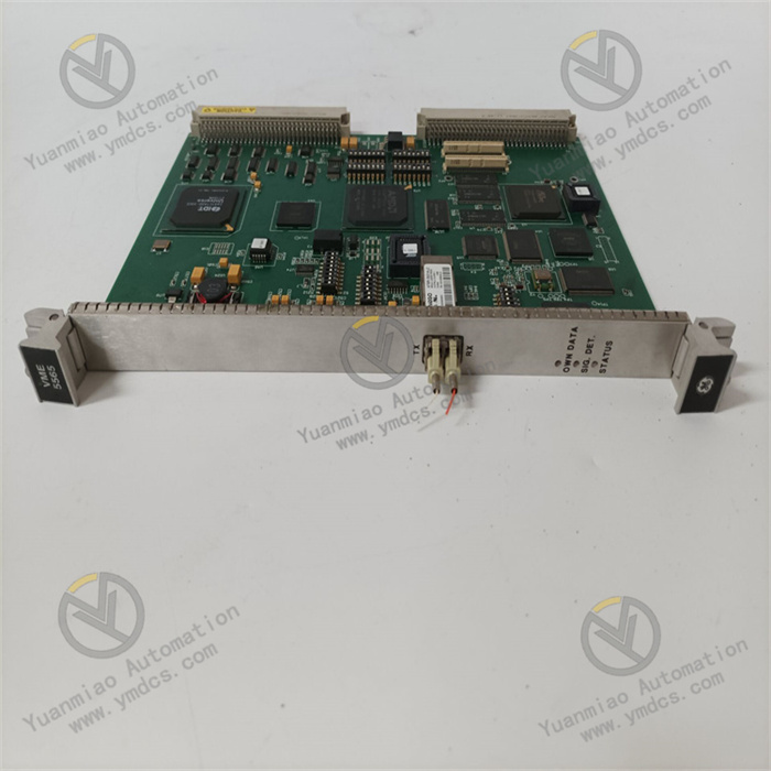
The GE IS215UCVEM01A is a multi-functional control voltage I/O module for the Mark VIe control system. Its core value lies in providing a solution for large rotating machinery (such as gas turbines, steam turbines, and combined cycle units) that enables "centralized hybrid signal processing, highly reliable voltage conversion, and seamless system integration". Serving as the "signal transfer hub" of the unit control system, it realizes the collection of voltage signals from on-site sensors (e.g., position feedback, status switches) and the output of control voltages for actuators (e.g., solenoid valve drive) through "multi-type signal interfaces, isolation protection, and redundancy design". It is suitable for the precise control needs of auxiliary systems in industries such as power generation, oil & gas, and metallurgy, and is a key component ensuring the stable operation of large-scale equipment.
This module adopts a modular plug-and-play design, supporting hot redundancy configuration and online maintenance of the Mark VIe system. When used with GE CIMPLICITY software, it enables parameter configuration and fault diagnosis. It is widely applied in the global large-scale turbine control field, especially suitable for auxiliary control loops requiring SIL 2 safety integrity level.
II. Technical Specifications
(I) Core Signal Processing Parameters
1. Input/Output Channel Configuration
Input Channels
8 universal control voltage input channels (compatible with 0-10V DC analog signals and 24V DC digital signals), configurable via software as follows:
- Analog Input: 0-10V DC (12-bit resolution, ±0.1% FS accuracy), suitable for potentiometer position feedback and voltage output of pressure sensors;
- Digital Input: 24V DC (high level: 18-30V, low level: 0-5V), suitable for limit switch and status indicator light signals.
Output Channels
4 control voltage output channels (24V DC/1A, with short-circuit protection), supporting:
- Digital Output: Drives solenoid valves and relay coils (maximum load: 1A per channel, total load ≤ 4A);
- Analog Output (software-configurable): 0-10V DC (12-bit resolution, ±0.2% FS accuracy), suitable for proportional valve control.
Channel Isolation
2500V AC isolation (with 1-minute voltage withstand capability) is provided between input channels, between output channels, and between input/output channels and the backplane. It resists common-mode interference voltage of ±250V DC, preventing signal crosstalk and ground loops.
2. Signal Response and Processing
- Input Response Time: ≤1ms for digital input (from signal transition to data update); ≤10ms for analog input (90% step response);
- Output Response Time: ≤5ms for digital output (from command to relay action); ≤50ms for analog output (90% step response);
- Filter Function: Input channels support software-adjustable filtering (1ms-100ms), which can eliminate signal fluctuations caused by on-site contact bounce or electromagnetic interference.
(II) Electrical and Power Supply Parameters
1. Power Supply Specifications
- Main Power Supply: 24V DC redundant power supply (compatible with 20-30V DC), drawing power from the Mark VIe I/O rack backplane. The rated power consumption of a single module is ≤15W (under full-load output);
- Output Power Supply: Built-in 24V DC output power supply (maximum 4A), which can power external sensors or actuators. It has overcurrent protection (1.2A per channel; automatic shutdown when total overcurrent reaches 5A);
- Protection Functions: Input overvoltage protection (clamping above 15V DC), output short-circuit protection (automatic channel cutoff in case of short circuit, self-recovery after fault elimination), and reverse polarity protection (no damage if power is connected in reverse).
2. Environmental Parameters
- Operating Environment: Temperature: 0-60℃ (no derating); storage temperature: -40-85℃; relative humidity: 5%-95% RH (no condensation); protection class: IP20 (must be installed in a closed cabinet);
- Electromagnetic Compatibility: Passed IEC 61000-4-2 (±8kV air discharge) and IEC 61000-4-4 (±2kV electrical fast transient) tests, adapting to the strong electromagnetic environment of turbine control rooms.
(III) Communication and System Compatibility Parameters
1. Communication Interfaces
- Backplane Communication: Communicates with controllers (e.g., IS200TBSCH1A) via the Mark VIe system's dedicated high-speed backplane bus (100Mbps). The data update cycle is ≤10ms, supporting deterministic real-time transmission;
- Redundancy Support: Supports module-level hot redundancy (requires 2 identical modules for automatic main-standby switching, with switching time ≤1ms), ensuring no interruption of critical signals;
- Diagnostic Communication: Built-in intelligent diagnostic chip, which can report channel faults, power status, communication quality, and other information via the backplane bus, supporting remote fault query.
2. System Adaptability
- Software Support: Compatible with GE CIMPLICITY HMI/SCADA software and Mark VIe ControlST programming environment, supporting graphical configuration of channel types, filter parameters, and alarm thresholds;
- Device Compatibility: Directly compatible with GE gas turbine sensors (e.g., 7EA/9FA series) and solenoid valves (e.g., fuel control valves), and compatible with third-party 24V DC devices (e.g., Siemens SIRIUS relays);
- Expansion Capability: A maximum of 8 IS215UCVEM01A modules can be installed in a single I/O rack. Through the Mark VIe network, it can be expanded to hundreds of I/O points, suitable for centralized control of large combined cycle power plants.
III. Functional Features
(I) Hybrid Signal Processing, Simplifying System Architecture
The hybrid channel design (8 inputs + 4 outputs) can process both analog and digital signals simultaneously, reducing the types of modules and cabinet space. For example, in a gas turbine auxiliary system, the module can collect:
- Analog Signals: Fuel pressure sensor (0-10V), lubricating oil temperature transmitter (0-10V);
- Digital Signals: Fuel valve limit switch (24V DC), filter clogging alarm (24V DC);
And output control signals to drive fuel solenoid valves (24V DC) and cooling fan relays (24V DC). Compared with discrete I/O modules, it reduces installation space and wiring by 50%.
(II) Highly Reliable Isolation and Protection, Withstanding Harsh Environments
The full-channel isolation design and multiple protection functions ensure stable operation under harsh environments such as turbine vibration, electromagnetic interference, and power fluctuations. In steam turbine control, when the module's output channel drives the solenoid valve of a steam trap, even if a cable short circuit occurs on-site (e.g., caused by condensed water), the module will cut off the output within 50ms and report a "short-circuit fault", preventing module damage and 连锁 shutdown. The input channel's overvoltage protection can withstand accidental 220V AC connection caused by sensor wiring errors, reducing on-site commissioning risks.
(III) Redundancy Design and Online Maintenance, Ensuring Continuous Operation
It supports hot redundancy configuration and hot-swap replacement, meeting the "non-stop maintenance" requirement of large units. In a combined cycle power plant, 2 IS215UCVEM01A modules redundantly collect steam turbine vacuum switch signals and drive the solenoid valve of the suction valve. When the main module fails, the standby module takes over automatically (switching time ≤1ms) without signal loss. Maintenance personnel can pull out the faulty module online, and parameters are synchronized automatically after inserting a new module (no reconfiguration required). The replacement time of a single module is ≤3 minutes, significantly reducing the risk of unplanned shutdowns.
(IV) In-depth System Integration, Improving Control Precision
As a native module of the Mark VIe system, it achieves seamless communication with the turbine controller, with data transmission delay ≤10ms, ensuring the real-time performance of control logic. During gas turbine startup, the analog fuel pressure signal (0-10V) collected by the module is calculated by the controller, and then the fuel control valve is adjusted in real-time through the output channel (0-10V analog output). The pressure control precision reaches ±0.2% FS, ensuring a stable startup process without overshoot. Combined with the trend analysis function of ControlST software, it can record the historical curve of channel signals, assisting engineers in optimizing control parameters.
IV. Application Fields
(I) Power Industry: Auxiliary Control of Gas/Steam Turbines
Gas Turbine Fuel System Control
The module collects the fuel pump outlet pressure (0-10V analog), fuel valve position feedback (0-10V), and filter differential pressure alarm (24V digital). It outputs signals to drive the fuel control valve (0-10V analog) and fuel pump start-stop relay (24V digital), realizing closed-loop fuel pressure control (control precision ±0.1bar).
Steam Turbine Lubrication System Monitoring
It collects the lubricating oil tank level (0-10V), oil pump operation status (24V), and high oil temperature alarm (24V). It outputs signals to control the cooler fan (24V). When the level is below the threshold, it triggers the startup of the standby pump, ensuring stable lubricating oil pressure.
(II) Oil & Gas Industry: Control of Compressors and Pumps
Natural Gas Compressor Auxiliary System
The module collects the compressor inlet pressure (0-10V), gas valve status (24V), and vibration switch alarm (24V). It outputs signals to drive the inlet guide vane control valve (0-10V) and vent valve solenoid valve (24V). When the pressure exceeds the limit, the vent valve is opened quickly (response time ≤100ms).
Oil Pipeline Pump Station Control
It collects the pump outlet pressure (0-10V) and filter clogging signal (24V). It outputs signals to control the pump's frequency conversion start-stop (24V) and bypass valve adjustment (0-10V). Through closed-loop pressure control, it ensures stable oil delivery (fluctuation ≤±2%).
(III) Metallurgy Industry: Auxiliary Equipment for Blast Furnaces and Rolling Mills
Blast Furnace Hot Blast Stove Control
The module collects the hot blast temperature (0-10V transmitter), combustion valve position feedback (0-10V), and gas pressure switch (24V). It outputs signals to control the gas valve (0-10V) and combustion air valve (0-10V), realizing precise air-fuel ratio adjustment (error ≤±3%).
Rolling Mill Hydraulic System Control
It collects the hydraulic station pressure (0-10V), oil tank level (0-10V), and pump operation status (24V). It outputs signals to control the hydraulic pump start-stop (24V) and relief valve adjustment (0-10V), ensuring stable rolling pressure (fluctuation ≤±0.5MPa).
V. Selection and Adaptation Recommendations
(I) Selection Criteria
Signal Type Matching
This module is preferred for scenarios requiring simultaneous processing of 0-10V analog signals and 24V DC digital signals (input + output). For pure analog or pure digital signal scenarios, dedicated modules (e.g., IS215UAVHM01A analog module) can be selected.
Load Capacity Adaptation
It is suitable for output-driven loads ≤1A per channel (e.g., solenoid valves, small relays). For heavy loads (e.g., contactors), external intermediate relays are required to avoid module overload.
Safety Level Requirement
For auxiliary control loops (e.g., lubrication, cooling systems) requiring SIL 2 level, redundant modules are recommended. For non-safety loops, a single module can be used.
(II) Peripheral Configuration Recommendations
Sensors and Actuators
- For analog input: Priority is given to GE original pressure/temperature transmitters (0-10V output);
- For digital input: 24V DC reed switch limit switches are selected;
- For output drive: Low-power solenoid valves (current ≤800mA, e.g., ASCO 8210 series) are selected.
Redundancy Configuration
For critical loops, 2 modules are required. The Mark VIe controller is used to realize signal comparison and main-standby switching. For redundant power supply, the GE IS200PWRCH1A redundant power module (24V DC/10A) must be selected.
Wiring Specifications
- Signal cables: Twisted shielded cables (cross-sectional area: 0.75mm²) are used;
- Analog and digital cables: Laid separately (distance ≥300mm);
- Shielding layer: Single-ended grounding (ground resistance ≤1Ω).
(III) Installation and Commissioning Notes
Installation Environment
The module must be installed in a Mark VIe standard I/O cabinet (e.g., IC698CAB100), avoiding direct sunlight and condensed water. The cabinet ventilation rate should be ≥10m³/h (to ensure the ambient temperature ≤60℃).
Parameter Configuration
- Configure channel types (analog/digital), input filter time (20ms recommended for analog signals, 5ms recommended for digital signals), and output overcurrent threshold (1.2A by default) via ControlST software.
Commissioning and Verification
- Simulate input signals (e.g., connect standard voltages of 0V, 5V, 10V) to verify collection accuracy;
- Connect a dummy load (24V/1A resistor) to the output terminal to verify output function;
- For redundant modules, test main-standby switching (disconnect the main module power supply and check if the standby module takes over the signal).