Description
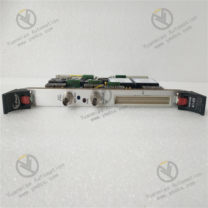
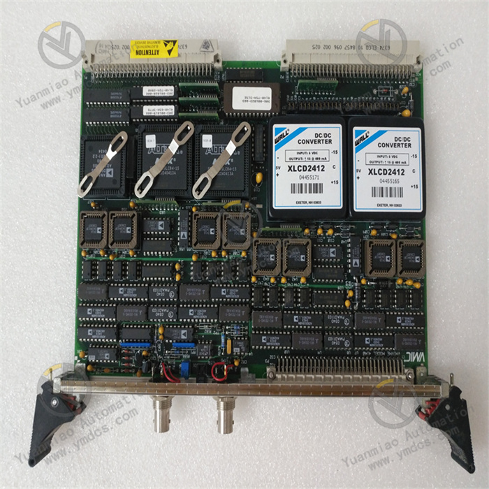
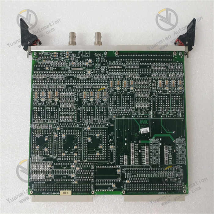
Abaco Systems VMIVME-4140
Overview
The Abaco Systems VMIVME-4140 is a high-performance analog output board based on the VME (VersaModule Eurocard) bus architecture, widely applied in industrial automation control, aerospace testing, defense signal simulation, and automatic test equipment (ATE). With its high-precision analog signal output capability, flexible configuration options, and reliable stability, it provides precise signal excitation and control signal output for complex systems, meeting high-precision and high-reliability application requirements. It serves as a core component for building professional-grade analog signal output systems.
Functional Features
High-Precision Analog Output
Equipped with multiple analog output channels, each channel is furnished with a high-resolution D/A converter to output stable and accurate analog signals. The precision and stability of the output signals meet the control requirements of precision equipment in industrial automation production lines and the high-precision requirements for analog signals in aerospace testing, ensuring the accuracy of system control and test results.
Flexible Output Configuration
- Supports various output voltage ranges, such as unipolar (0 to +10V, 0 to +5V, etc.) and bipolar (±5V, ±10V, etc.), which can be flexibly configured via software to adapt to the input signal requirements of different devices.
- Offers diverse output update modes, including random update and synchronous update, to meet real-time or synchronous signal output needs based on actual application scenarios. For example, it enables synchronous signal output in multi-device collaborative testing systems.
Excellent Electrical Performance
- Features low output impedance to reduce signal attenuation and distortion during transmission, ensuring signal quality. It maintains stable signal output even in long-distance transmission or complex electromagnetic environments.
- Exhibits good anti-interference capability. Using technologies such as electrical isolation, it effectively resists external electromagnetic interference, ensuring the purity and stability of output signals, making it suitable for industrial and military applications with harsh electromagnetic environment requirements.
Convenient Calibration and Diagnosis
- Built-in automatic calibration function can be initiated via software commands or system reset, automatically calibrating each channel to compensate for signal deviations caused by factors such as temperature changes and component aging, ensuring long-term output accuracy.
- Equipped with a complete self-check and diagnosis function, it real-time monitors the board's working status, such as power voltage and channel performance. Upon detecting faults, it feedbacks fault information through status indicator lights and error codes, facilitating quick location and elimination of faults, and reducing maintenance costs and time.
Working Principle
Analog Signal Generation and Output
When the system needs to output analog signals, the host transmits digital signals to the VMIVME-4140 board via the VME bus. The control logic within the board receives the digital signals and distributes them to the corresponding D/A converters. The D/A converters convert the digital signals into corresponding analog voltage or current signals based on their numerical values. The converted analog signals undergo processing such as filtering, amplification, and impedance matching through signal conditioning circuits to optimize signal quality and driving capability. Finally, they are output to external devices via output interfaces to achieve device control or signal excitation.
Calibration and Diagnosis Mechanism
- Automatic Calibration: The board's internal calibration circuit generates a series of standard test signals and outputs them to each analog channel. Simultaneously, it collects the actual output signals of each channel through internal feedback circuits, compares and analyzes them with standard signals, calculates the offset and gain errors of each channel, generates calibration coefficients, and stores them in the board's non-volatile memory. During normal operation, the board real-time corrects the output signals based on these calibration coefficients to ensure output accuracy.
- Self-Check and Diagnosis: Through built-in monitoring circuits, it continuously detects the board's key components and working parameters (e.g., whether the output voltage of the power module is within the normal range, whether the working status of the D/A converter is abnormal, etc.). Upon discovering abnormalities, the diagnosis circuit generates corresponding error codes, displays fault information through status indicator lights, and feedbacks the error codes to the host, enabling users to take timely measures for fault handling.
Common Faults and Solutions
| Fault Symptom | Possible Causes | Solutions |
|---|---|---|
| Analog output signal abnormality (e.g., inaccurate voltage, large signal fluctuations) | 1. Uncalibrated in time or calibration data loss 2. D/A converter failure 3. Signal conditioning circuit failure 4. External electromagnetic interference | 1. Reperform automatic calibration to restore calibration data; 2. Use diagnostic tools to detect the D/A converter and contact professionals for replacement if damaged; 3. Check the signal conditioning circuit, troubleshoot and repair or replace faulty components; 4. Shield the board and related equipment, keep away from interference sources, or add filtering devices to reduce interference. |
| No output signal from partial channels | 1. Channel hardware damage 2. Output connection cable failure 3. Channel configuration error | 1. Use the board's self-check function to locate faulty channels and replace damaged hardware components; 2. Check output cables, ensure secure connections, and replace damaged cables; 3. Check channel configuration parameters to ensure correct settings for output mode, range, etc. |
| Board failure to communicate with the system (abnormal VME bus communication) | 1. Loose or poor contact of VME bus connection 2. VME bus address conflict 3. Board communication interface failure | 1. Check the VME bus connector, re-plug to ensure a secure connection; 2. Check the VME bus address settings of each device in the system, avoid address conflicts, and correct incorrect addresses; 3. Use the substitution method to detect the communication interface and contact the manufacturer for maintenance or board replacement if faulty. |
| Abnormal display of board status indicator lights | 1. Damaged indicator lights 2. Internal diagnostic circuit failure 3. Abnormal board power supply | 1. Replace damaged indicator lights; 2. Detect the internal diagnostic circuit and repair or replace faulty components; 3. Use a multimeter to detect the board's power input voltage, check the power module and power supply lines, and repair power faults. |