Description
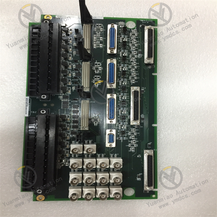
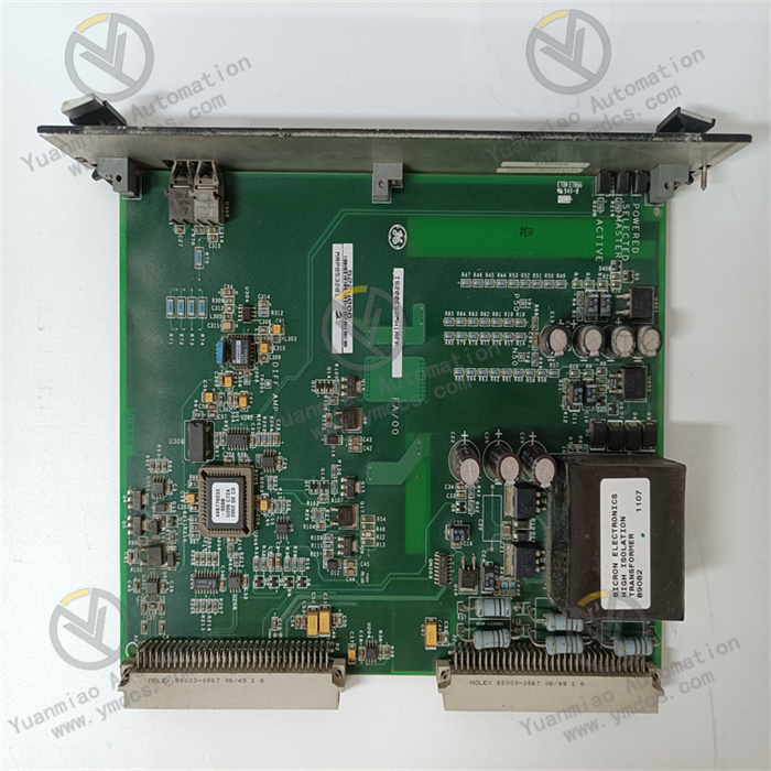
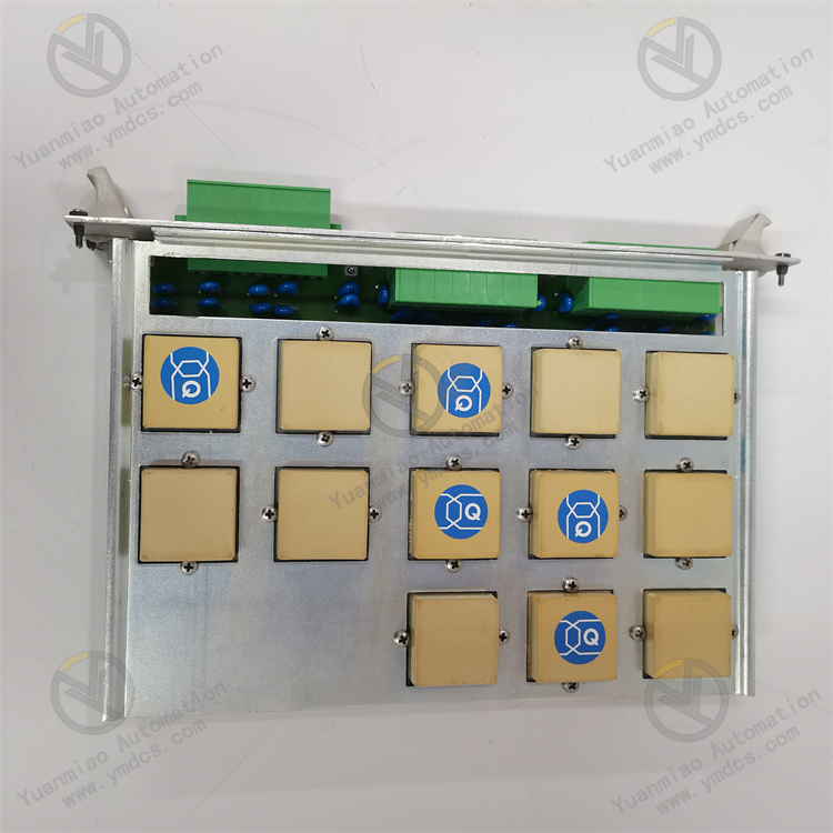
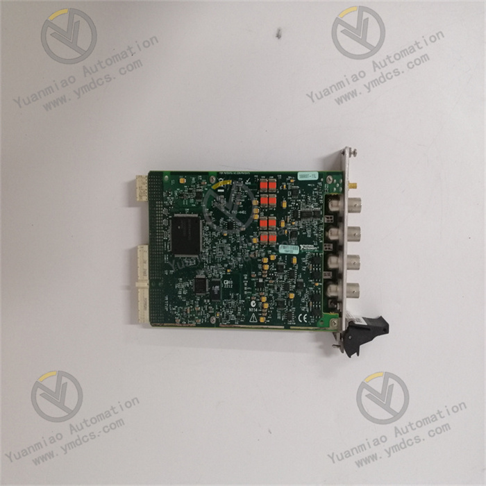
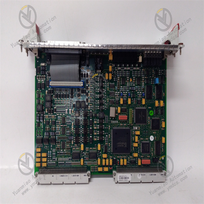
GE IS215VCMIH2BE
I. Overview
GE IS215VCMIH2BE is an industrial-grade dedicated valve control module for steam turbine control systems. Its core value lies in providing a closed-loop control solution of "control signal analysis - drive command generation - valve status feedback" for key valves of steam turbines (such as high-pressure main steam valves, medium-pressure control valves, low-pressure supplementary steam valves, etc.). Serving as the "signal processing and execution hub" for valve control, it achieves high-precision adjustment of valve opening (control accuracy of ±0.1%) and real-time status monitoring. It is suitable for valve control scenarios of 300MW-1000MW thermal power units and gas turbines in combined cycle power plants, and is a key component ensuring precise control of steam turbine intake volume and improving the operational stability of the unit.
This module adopts a reinforced valve drive circuit and a mixed-signal processing architecture, supporting seamless integration with the Mark VIe main control system and various valve actuators (such as servo valves, electro-hydraulic actuators). It combines signal processing accuracy with drive response speed, and is a core unit in the Mark VIe system for realizing refined control of steam turbine valves.
II. Technical Parameters
(I) Valve Control Signal Processing and Drive Parameters
1. Signal Input and Output Configuration
- Analog Input (Valve Status Feedback): 8 channels of high-precision analog input (16-bit AD, input range of ±10V DC/4-20mA) for collecting key valve status parameters:
- Valve Opening Feedback: Current opening (0-100%, corresponding to 4-20mA or ±10V, from the actuator position sensor);
- Drive Cylinder Pressure: Servo valve control oil pressure (0-20MPa, converted to 4-20mA via a pressure transmitter);
- Actuator Temperature: Oil motor temperature of the electro-hydraulic actuator (0-100℃, RTD signal conditioned to 4-20mA);Input accuracy is ±0.03% FS, with a sampling rate of 100Hz (adapting to the dynamic adjustment needs of valves) to ensure no deviation in status feedback.
- Analog Output (Valve Drive Command): 6 channels of high-precision analog output (16-bit DA, output range of ±10V DC/4-20mA) for sending drive commands to actuators:
- Servo Valve Control: Opening command (±10V, controlling the spool displacement of the servo valve, corresponding to 0-100% valve opening);
- Electro-Hydraulic Actuator Drive: Proportional valve control signal (4-20mA, adjusting the oil intake of the cylinder);Output accuracy is ±0.05% FS, output response time ≤50μs (quickly responding to main control adjustment commands), and drive signal linearity ≥0.02%.
- Digital I/O (Valve Interlock and Status): 16 channels of digital input (24V DC, collecting valve limit switch signals, pressure switch status, actuator fault alarms), 12 channels of digital output (24V DC, driving valve interlock solenoid valves, indicator lights, and outputting emergency valve closing commands), with a response time ≤1ms (ensuring rapid triggering of interlock signals).
2. Valve Control Performance
- Control Algorithms: Built-in library of dedicated control algorithms for steam turbine valves, including:
- Nonlinear Compensation PID: Aiming at valve dead zone and hysteresis characteristics, dynamically correcting PID parameters to improve control accuracy to ±0.1%;
- Opening Feedforward Control: Outputting opening commands in advance based on the unit load command to reduce adjustment lag, with overshoot ≤2%;
- Valve Characteristic Curve Correction: Supporting software configuration of valve flow characteristic curves (such as linear, equal percentage) to adapt to different valve types.
- Adjustment Cycle: Minimum control cycle of 1ms (high-frequency adjustment, adapting to rapid load change scenarios), and the full-stroke response time of valve opening from 0 to 100% ≤50ms (meeting the rapid valve closing requirement when the steam turbine sheds load).
- Safety Protection: Built-in valve jamming detection logic (when the deviation between command and feedback >3% and lasts for 500ms, it is determined as jamming and an alarm is triggered). It supports the highest priority of emergency valve closing commands (not affected by conventional control logic, valve closing time ≤100ms).
(II) Communication and Redundancy Parameters
1. Communication Interfaces and Protocols
- Internal Communication (with Mark VIe Main Control): Dual optical fiber interfaces (100Mbps speed, supporting GE SRTP protocol) for redundant communication with the main controller (e.g., IS200TBSCH1A), with a data update cycle ≤1ms (ensuring real-time interaction between control commands and status feedback).
- External Communication (with Actuators): 1 EtherNet/IP port (10/100Mbps, compatible with the standard communication protocol of electro-hydraulic actuators), 1 RS-485 port (supporting Modbus RTU protocol for connecting local valve monitoring instruments).
- Synchronization Interface: 1 IRIG-B code input (time synchronization accuracy of ±1ms) to ensure the action consistency of multi-valve control (such as coordinated adjustment of high-pressure control valves and medium-pressure control valves).
2. Redundancy Configuration
- Communication Redundancy: Dual optical fiber links + EtherNet/IP backup link. When the main link fails, the backup link switching time ≤100μs (no control interruption, avoiding valve adjustment failure).
- Power Redundancy: Dual-channel 24V DC redundant power supply (input range of 18-30V DC). The power consumption of a single module is ≤10W (under full-load drive), and the power switching time ≤10μs (no power supply interruption).
- Signal Redundancy: Key analog inputs (such as valve opening feedback) support dual-channel acquisition and difference comparison (an alarm is triggered when the deviation >2%), avoiding control failure caused by a single sensor fault.
(III) Electrical and Environmental Parameters (Suitable for Steam Turbine Control Room Scenarios)
1. Isolation and Anti-Interference
- Isolation Performance:
- Signal Isolation: 2500V AC isolation (1-minute voltage withstand) between analog I/O and communication interfaces; 1500V AC isolation between digital I/O and internal circuits. It resists a common-mode interference voltage of ±500V DC (combating strong electromagnetic interference from actuators).
- Power Isolation: 2000V AC isolation between the input power supply and internal circuits, with power ripple suppression ≤50mV (peak-to-peak) to ensure stable drive signals.
- Electromagnetic Compatibility: Passes IEC 61000-4 tests, withstanding ±15kV air discharge (ESD), ±4kV electrical fast transients (EFT), and 30V/m radio frequency interference (RFI), adapting to the electromagnetic environment with multiple devices in the steam turbine control room.
2. Environmental Adaptability
- Operating Environment: Temperature range of -10℃ to 65℃ (operation without derating), storage temperature range of -40℃ to 85℃, relative humidity of 5%-95% RH (no condensation), adapting to installation scenarios in control rooms and on-site control cabinets.
- Protection Design: The module itself has an IP20 protection rating (to be installed in a Mark VIe standard rack). The PCB board is coated with a reinforced conformal coating (oil-proof and dust-proof, adapting to the steam turbine lubricating oil mist environment).
- Anti-Vibration Performance: Complies with IEC 60068-2-6 standard, with a vibration acceleration of ≤20m/s² at 10Hz-2000Hz. The Mean Time Between Failures (MTBF) is ≥180,000 hours.
(IV) System Compatibility and Diagnostic Parameters
1. System Adaptability
- Software Support: Compatible with GE Mark VIe ControlST V10.0 and above versions, supporting graphical configuration of valve control parameters (such as PID parameters, characteristic curves) and redundancy strategies, and providing dedicated valve diagnostic function blocks (such as jamming detection, over-travel protection).
- Device Compatibility: Directly compatible with mainstream actuators such as GE Hydraulic Servo valves, Moog electro-hydraulic actuators, and Siemens valve positioners, without the need for dedicated drivers.
- Installation Method: Supports installation in Mark VIe standard I/O racks (size: 120mm×150mm×30mm), compatible with other IS series modules, requiring no additional installation space.
2. Diagnosis and Maintenance
- Local Diagnosis: The panel is equipped with 12 LED indicators (Power, Comm A/B, AO Fault, Valve Jam, Emergency). For example, "flashing red Valve Jam light" indicates valve jamming, and "steady red Emergency light" indicates the triggering of an emergency valve closing command.
- Remote Diagnosis: Supports remote query of real-time valve opening, drive current, and fault codes (e.g., "E01" represents loss of opening feedback) via the Mark VIe main control. It allows online calibration of analog input/output accuracy (calibration error ≤±0.02% FS).
- Maintenance Function: Built-in valve static test mode (triggered by software, outputting fixed opening commands to test valve response characteristics), requiring no external test equipment and simplifying the regular verification process.
III. Functional Features
(I) High-Precision Valve Drive, Adapting to Steam Turbine Load Change Adjustment
With 6 channels of high-precision analog output and nonlinear compensation algorithms, it can achieve micron-level control of valve opening, meeting the precise adjustment needs of steam turbines over a wide load range. In the control of high-pressure control valves for 600MW thermal power units:
- The module receives the load command issued by the main control (e.g., increasing from 300MW to 600MW), and through feedforward-feedback composite control, outputs the opening command in advance and dynamically corrects it based on feedback. The adjustment time for the control valve opening to increase from 50% to 100% is ≤300ms, with overshoot ≤1%, avoiding main steam pressure fluctuations (pressure fluctuation ≤±0.2MPa).
- Aiming at the dead zone characteristic of control valves (usually 0.5%-1%), the module eliminates the impact of the dead zone through a software compensation algorithm, improving the control accuracy from ±0.5% to ±0.1%, and the unit load control accuracy is increased to ±1MW, meeting the grid AGC frequency regulation requirements.
(II) Mixed-Signal Processing, Connecting the Closed-Loop Link of Valve Control
It integrates mixed analog/digital input and output, realizing full-link control of valves including "command issuance - status feedback - interlock protection" and simplifying the system architecture. In the control of gas turbine fuel valves in combined cycle power plants:
- The analog output channel sends a ±10V drive command to the fuel valve servo valve to control the fuel flow rate (0-50m³/h); at the same time, the analog input channel collects the valve position feedback (4-20mA) and post-valve pressure (4-20mA) to form dual closed-loop control (flow-pressure), with the fuel flow control accuracy of ±0.1m³/h.
- The digital input collects the "overpressure alarm" (24V DC) signal of the fuel valve, triggering the digital output channel to drive the interlock solenoid valve, cutting off the fuel supply within 1ms to avoid the risk of gas turbine deflagration. Compared with traditional relay interlocks, the response speed is increased by 10 times.
(III) Strong Anti-Interference and Rapid Protection, Ensuring Valve Operation Safety
The reinforced electromagnetic isolation design and emergency valve closing logic ensure the reliability and safety of valve control in a strong interference environment. In the control of high-pressure main steam valves for 1000MW supercritical units:
- The 30V/m radio frequency interference generated by high-voltage motors near the main steam valve does not affect the module's drive signal output (±10V signal error ≤±0.01V), and the control accuracy of the main steam valve opening does not degrade.
- When the steam turbine overspeeds (rotational speed >3300r/min), the module receives the emergency valve closing command from the main control and outputs the valve closing signal within 100μs. The full closing time of the main steam valve is ≤50ms (much lower than the safety standard of 100ms), avoiding unit overspeed accidents.
(IV) Intelligent Diagnosis and Maintenance, Reducing Operation and Maintenance Costs
Built-in functions such as valve jamming detection and online calibration provide early fault warning and simplify the maintenance process. In the maintenance of steam turbine control valves in biomass power plants:
- The module continuously monitors the deviation between the command and feedback. When the deviation >3% and lasts for 500ms, it is determined as valve jamming and an alarm is reported. Maintenance personnel can arrange repairs in advance to avoid unplanned shutdowns (each shutdown causes a loss of approximately 50,000 yuan).
- The valve static test is remotely initiated through ControlST software, which automatically outputs 0%-100% opening commands and records the feedback curve to determine whether the valve linearity meets the standard. The verification time is shortened from the traditional 4 hours to 30 minutes, increasing the operation and maintenance efficiency by 80%.
IV. Application Fields
(I) Thermal Power Industry: Steam Turbine Valve Control
- 300MW-600MW Subcritical Units: The module controls high-pressure main steam valves and medium-pressure control valves, collects valve position feedback (4-20mA) and cylinder pressure (0-16MPa), and outputs ±10V commands to servo valves through PID adjustment. The control accuracy of the main steam valve opening is ±0.1%, ensuring stable main steam flow and increasing the unit thermal efficiency by 0.3%.
- 1000MW Supercritical Units: Equipped with dual-module redundancy (master-standby mode), it controls low-pressure supplementary steam valves and reheat steam valves, and communicates with electro-hydraulic actuators via EtherNet/IP to realize coordinated valve adjustment (the action time difference between supplementary steam valves and main steam valves ≤10ms), meeting the rapid load change requirements of supercritical units (load change rate ±2%/min).
(II) Combined Cycle Power Plants: Gas Turbine Fuel Valve Control
- F-Class Gas Turbines: The module controls fuel control valves (natural gas/fuel oil), collects valve position feedback and fuel pressure signals, and adjusts the valve opening in advance through feedforward control. When the load increases from 30% to 100%, the fuel flow adjustment response time is ≤200ms, avoiding combustion chamber temperature fluctuations (fluctuation range ±5℃) and extending the service life of hot components.
- Distributed Combined Cycle Power Plants: The module connects to the local HMI via RS-485 to display real-time fuel valve status (opening, pressure), and uploads data to the remote Mark VIe main control via optical fiber, realizing "local monitoring + remote control" and adapting to the decentralized layout of distributed power plants.
(III) New Energy: Steam Turbine Control in Biomass/Waste Incineration Power Plants
- Biomass Power Plants: Aiming at the unstable intake volume caused by biomass fuel fluctuations, the module captures valve position feedback fluctuations through 100Hz high-frequency sampling and dynamically corrects drive commands. The intake volume fluctuation range is reduced from ±5% to ±1%, and the steam turbine speed is stabilized at 3000r/min±1r/min.
- Waste Incineration Power Plants: The anti-corrosion coating on the module's PCB board resists corrosive gases generated by incineration. It controls the steam turbine extraction valve, collects the post-valve steam pressure (0-1MPa), and ensures stable extraction pressure through cascade adjustment (pressure-opening) to meet the steam demand of the waste heat boiler.
(IV) Grid Peak-Shaving: Hydraulic Turbine Control in Pumped Storage Power Plants
- Power Generation Mode: The module controls the hydraulic turbine guide vanes, collects guide vane opening (0-100%) and inlet pressure (0-10MPa), and outputs 4-20mA commands to electro-hydraulic actuators through PID adjustment. The guide vane opening control accuracy is ±0.1%, and the hydraulic turbine output fluctuation is ≤±0.5MW.
- Pumping Mode: It receives the "pumping-power generation" switching command and completes the switching of guide vanes from "fully closed" to "fully open" within 150ms. There is no pressure impact during the switching process (pressure fluctuation ≤±0.2MPa), protecting the hydraulic turbine flow components.


