Description
Working Principles:
Traction Converter: Converts electrical energy input from the power grid into frequencies and voltages suitable for motor operation, thereby driving train traction motors. For example, for a power grid with an input voltage of AC 25kV, the traction converter uses internal power conversion circuits to transform it into voltages and frequencies appropriate for train traction motors, enabling speed regulation and control of the motors. It also features energy feedback technology, which feeds back the electrical energy generated by the motors during train braking to the power grid, improving energy efficiency.
Traction Converter: Converts electrical energy input from the power grid into frequencies and voltages suitable for motor operation, thereby driving train traction motors. For example, for a power grid with an input voltage of AC 25kV, the traction converter uses internal power conversion circuits to transform it into voltages and frequencies appropriate for train traction motors, enabling speed regulation and control of the motors. It also features energy feedback technology, which feeds back the electrical energy generated by the motors during train braking to the power grid, improving energy efficiency.
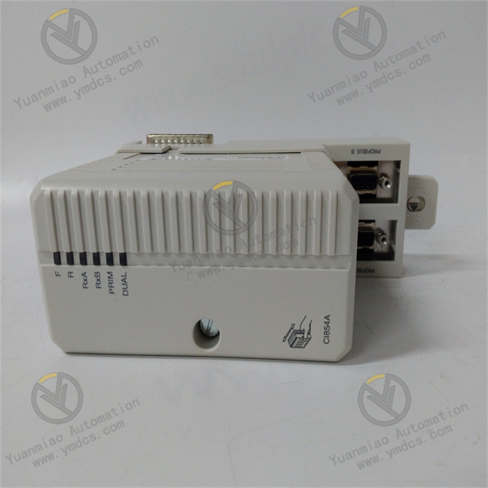
High-Voltage Contactor: Controls the opening and closing of contacts through an electromagnetic mechanism to connect or disconnect high-voltage circuits. When the electromagnetic coil is energized, it generates a magnetic field that attracts the armature, closing the contacts and connecting the high-voltage circuit. When the electromagnetic coil is de-energized, the magnetic field disappears, and the armature resets under spring force, opening the contacts and cutting off the high-voltage circuit. It has strong arc-extinguishing capabilities, capable of quickly extinguishing arcs when disconnecting high-voltage circuits to protect equipment and personnel safety. It is also vibration-resistant, suitable for frequent operation scenarios during train travel.
Signal System Components: Transmit train position, speed, and other information through wireless communication (e.g., GSM-R) or track circuits to achieve train operation control. Signal system components continuously exchange information with ground equipment or other trains, controlling train operating speeds, stopping positions, etc., based on received information and preset rules to ensure safe and efficient train operation. For example, track circuits detect whether a train occupies a track, and the GSM-R network receives dispatch instructions and position information of other trains to enable precise train control. They comply with ETCS (European Train Control System) standards and feature fail-safe designs, capable of taking safety measures during faults to ensure train operation safety.
Common Faults and Solutions
I. Electrical Faults
- No Power Supply or Failure to Start
- Check Power Supply: Use a multimeter to measure whether the input voltage meets rated parameters (e.g., DC 1500V/AC 25kV), and inspect power supply lines for damage or poor contact.
- Inspect Protection Devices: Replace blown fuses and reset circuit breakers. If tripping recurs, check for overloads or short circuits.
- Check Control Circuits: Tighten wiring terminals, use an oscilloscope to detect control signals, and restart the PLC or re-download the program.
- Abnormal input power (e.g., unstable voltage, phase loss, open circuit).
- Blown fuses, tripped circuit breakers, or faulty power modules.
- Loose control circuit wiring, poor terminal contact, or abnormal PLC programs.
- Possible Causes:
- Solutions:
- Abnormal Heating or Odor
- Shutdown Inspection: Disconnect power, observe component appearance (e.g., capacitor swelling, burnt wiring), and replace damaged parts (professional operation required).
- Clean Cooling Systems: Clean dust from cooling vents, test fan operation, and replace fans if they stop or make unusual noises.
- Detect Loads and Contact Points: Use an infrared thermometer to check contact temperatures. If overheated, sandblast oxidation layers or replace connectors; check if loads exceed rated power (e.g., 3000kW) and reduce non-essential loads.
- Aging internal components (e.g., swollen capacitors, burnt resistors) or poor heat dissipation.
- Oxidized or loose contact points causing excessive contact resistance, or loads exceeding rated power.
- Faulty fans, blocked cooling vents, or excessively high ambient temperatures (beyond -25°C ~ +70°C).
- Possible Causes:
- Solutions:
- Frequent Tripping or Protection Activation
- Reset Protection Parameters: Re-set overcurrent/overvoltage thresholds per the manual (e.g., restore default values) to avoid false triggers from too-low thresholds.
- Inspect Insulation and Short Circuits: Use an insulation tester to measure wiring insulation resistance (should be ≥2MΩ), and repair or replace damaged cables.
- Investigate Mechanical Loads: Manually rotate the motor shaft to check for jams, and contact the mechanical team to inspect transmission components.
- Improper setting of overcurrent/overvoltage protection thresholds, or equipment short circuits/ground faults.
- Mechanical jamming in motors or loads causing sudden current surges.
- Damaged wiring insulation (e.g., failure of protection class IP54/IP65, allowing dust/water intrusion).
- Possible Causes:
- Solutions:
II. Mechanical Faults
- Abnormal Vibration or Noise
- Tighten Mounting: After shutdown, check all bolt torques, use a level to adjust equipment installation, and reinforce brackets.
- Lubricate and Replace Components: Add gearbox lubricant per manual specifications, replace worn bearings or gears; check fan blades for deformation and adjust or replace fans.
- Calibrate Alignment: Use a laser alignment tool to calibrate motor and load shafts, ensuring coaxiality error ≤0.1mm.
- Loose mounting bolts, deformed brackets, or unlevel equipment fixation.
- Worn transmission components (e.g., oil-deficient gearboxes, damaged bearings) or loose fan blades.
- Excessive misalignment between the motor and load shafts (e.g., uncalibrated couplings).
- Possible Causes:
- Solutions:
- Failure to Actuate or Sticking (e.g., Contactor Contacts Not Engaging)
- Test Electromagnetic Coils: Use a multimeter to measure coil resistance (refer to manual standard values); replace coils if open-circuited or with abnormal resistance.
- Clean and Lubricate Mechanical Parts: Disassemble contactors, remove foreign matter between contacts, clean surfaces with anhydrous alcohol, and apply a small amount of conductive paste; replace aging springs or entire components.
- Inspect Arc Extinguishing Systems: Immediately replace cracked or carbonized arc extinguishers to prevent arc faults.
- Burnt electromagnetic coils, missing control signals, or insufficient power voltage (e.g., below 85% of rated voltage).
- Rusty mechanical parts, foreign matter jams (e.g., dust in contacts), or aging springs losing elasticity.
- Damaged arc extinguishers causing contact adhesion or failed disconnection.
- Possible Causes:
- Solutions:
III. Communication Faults
- Data Transmission Interruptions or Errors (e.g., MVB, Ethernet Interfaces)
- Check Physical Connections: Replace damaged cables, reinsert and secure interfaces, and repair bent pins with specialized tools.
- Configure Parameters and Upgrade Firmware: Ensure master-slave device parameters match per the manual (e.g., MVB baud rate 1.5Mbps), and update communication module firmware via a host computer.
- Anti-Interference Measures: Use shielded cables with reliable grounding, keep away from high-voltage lines, or add electromagnetic shielding.
- Damaged communication cables, loose interfaces, or bent connector pins.
- Mismatched communication protocols (e.g., baud rate, slave address conflicts) or outdated module firmware.
- Electromagnetic interference (e.g., near high-voltage equipment) causing signal distortion.
- Possible Causes:
- Solutions:
- Abnormal Sensor Signals (e.g., Distorted Temperature/Position Data)
- Clean and Calibrate: Clean probes with alcohol-dipped lint-free cloths, and readjust installation distances with specialized fixtures (e.g., proximity switches maintain 5-10mm detection gaps).
- Test Power Supply and Signals: Measure sensor supply voltage stability (e.g., DC 24V±10%), observe output signal waveforms with an oscilloscope, and replace sensors if abnormal.
- Replace Transmission Lines: Use low-impedance shielded cables, shorten signal lines, or add signal repeaters.
- Contaminated sensor probes (e.g., dust/oil blocking detection windows) or shifted installation positions.
- Unstable sensor power supply (e.g., voltage fluctuations) or aging internal components.
- Mismatched signal transmission line impedance or electromagnetic interference.
- Possible Causes:
- Solutions:
IV. Safety Precautions
High-Voltage Operation Safety:
- For high-voltage components (e.g., AC 25kV converters), disconnect power first, hang "Do Not Close" signs, and wait for capacitor discharge (≥5 minutes) before work.
- Wear insulating gloves, boots, and other protective gear; use qualified high-voltage voltage detectors to confirm no voltage is present.
Professional Operation Requirements:
- Alstom rail transit equipment is the safety-critical system; unauthorized personnel are prohibited from disassembly or parameter modification. Maintenance must be performed by technicians with EN 50155 and other relevant qualifications.
Recording and Feedback:
- After each fault resolution, detailed record the time, symptoms, causes, and replaced parts (e.g., "Replaced TRVC062333000 contactor coil") and file them in the equipment archive.
- If similar faults occur frequently (e.g., ≥2 times monthly), immediately contact Alstom technical support to investigate design defects or installation issues.