Description
GE IS200VCMIH2BEE
I. Product Overview
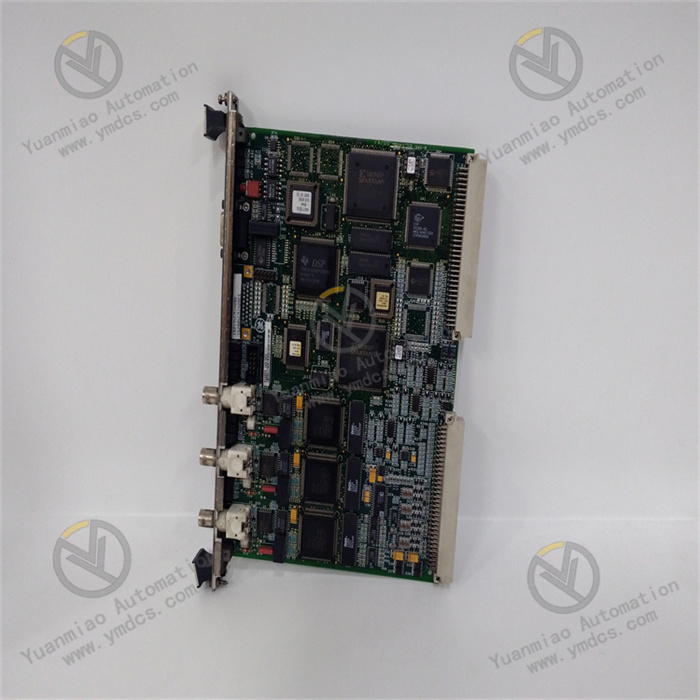
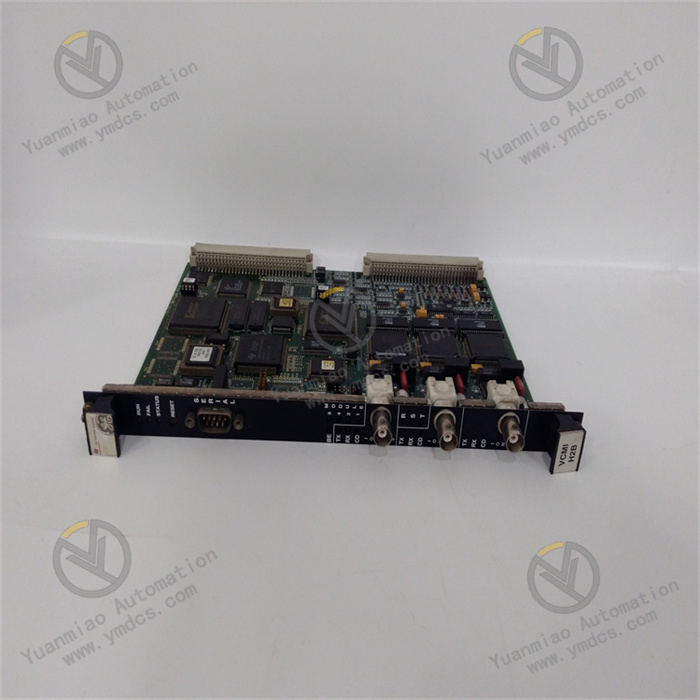
GE IS200VCMIH2BEE is the core main control module in the Mark VIe series digital control system for steam turbines. As the "computation and decision-making hub" of the entire control system, it is specifically designed for centralized control scenarios of key power equipment such as large-scale steam turbine generator units and gas-steam combined cycle units. Its core functions include receiving and processing on-site data from various I/O modules (e.g., analog input module IS200VAICH1DAB, analog output module IS200TVBAH2ABC), executing preset control logic (such as steam turbine speed regulation, load adjustment, start-stop control), issuing precise control commands to actuators, and simultaneously realizing system status monitoring, fault diagnosis, and data interaction with upper-level systems. This module is widely used in fields with strict requirements for control response speed, reliability, and redundancy capabilities, including thermal power generation, combined cycle power generation, nuclear power auxiliary power systems, and large-scale industrial captive power plants.
II. Functional Features
- High-Performance Multi-Core Computing and Real-Time ControlIt adopts a dual-core 32-bit industrial-grade processor, where the main core is responsible for control logic computation, and the secondary core handles data preprocessing and communication management. With an operating frequency of 800MHz, a single module can support real-time processing of up to 512 I/O signals, and the control cycle can be flexibly configured within the range of 1ms-100ms to meet the response requirements of different control scenarios. For example, in steam turbine speed regulation control, the speed control cycle can be set to 1ms to ensure the speed fluctuation is controlled within ±1rpm; in load adjustment scenarios, a 10ms control cycle is adopted to achieve a load adjustment accuracy of ±0.5% of the rated load. The module has a built-in Floating-Point Unit (FPU) that supports high-speed computation of complex control algorithms, such as multi-variable predictive control in coordinated control and rotor stress calculation of steam turbine generator units, with a computation error of ≤0.01%, providing core support for precise control.
- Full Redundancy Architecture and High-Reliability DesignIt adopts a "1+1" hot-standby redundancy architecture, supporting parallel operation of dual modules. Real-time data synchronization between the two modules is achieved through a high-speed synchronization link (synchronization rate ≤100ns). When the main module fails, the standby module can seamlessly switch to the main control state within ≤1ms. During the switching process, control commands remain uninterrupted and undisturbed, ensuring stable unit operation. The module also features power supply redundancy (dual independent DC 24V power supplies) and communication redundancy (multi-channel Genius bus + EtherNet/IP redundant links). All key components (such as processors, memories, and communication chips) use industrial-grade high-reliability devices, complying with the IEC 61508 safety standard, with a Mean Time Between Failures (MTBF) of ≥500,000 hours, meeting the reliability requirements of nuclear-grade auxiliary systems.
- Flexible I/O Adaptation and Expansion CapabilityIt is equipped with abundant communication interfaces and can directly connect to various I/O modules of the Mark VIe series, including analog input/output modules, digital input/output modules, and pulse input modules. It supports multiple industrial communication protocols such as Genius bus, EtherNet/IP, and Modbus TCP. A single module can manage up to 32 slave I/O modules, expanding to 2048 I/O signals. The module supports a "master-slave" distributed control architecture, and collaborative control of multiple main control modules can be realized through a redundant communication network, making it suitable for centralized control scenarios of multi-unit joint operation (such as captive power plants with multiple parallel steam turbines). Meanwhile, the module reserves standard API interfaces, enabling seamless connection with third-party monitoring systems (such as SCADA and DCS) to achieve data intercommunication and remote monitoring.
- Visual Configuration and Flexible ProgrammingIt supports full-function configuration and programming through GE ControlST V7.0 and above configuration software. The software provides a graphical programming interface and supports multiple programming methods such as Ladder Diagram (LD), Function Block Diagram (FBD), and Structured Text (ST), adapting to the programming habits of different engineers. It has a built-in rich library of dedicated function blocks for steam turbine control, such as speed regulation blocks, load distribution blocks, valve control blocks, and trip logic blocks. Engineers can directly call these function blocks to quickly build control logic, reducing repetitive development workload. The software supports online modification and downloading of control logic (authorization required). The modification process does not affect normal system operation, and logic switching is only executed after the download is completed, ensuring the convenience of debugging and maintenance.
- Full-Link Diagnosis and Fault ToleranceA three-level diagnosis system ("module-level - network-level - system-level") is constructed, with a diagnostic coverage rate of 99.95%. Module-level diagnosis monitors the working status of core components such as processors, memories, power supplies, and communication interfaces in real time, performing a self-check every 5ms. When a component failure (such as abnormal processor computation or memory read/write error) is detected, it immediately triggers redundancy switching and uploads fault information. Network-level diagnosis monitors the communication status with I/O modules and upper-level systems in real time through communication check codes and heartbeat detection mechanisms. When communication interruption or a packet loss rate of ≥0.5% is detected, it automatically switches to the standby communication link and records fault logs. System-level diagnosis analyzes the execution status of control logic (such as PID output exceeding limits or unmet interlocking conditions) and provides early warning of potential risks (such as steam turbine over-temperature and over-pressure trends). All diagnostic information can be displayed through local indicator lights or uploaded to the operation & maintenance platform, supporting the storage of 2000 fault logs, including fault time, fault location, fault level, and handling suggestions.
- Real-Time Data Management and InteractionIt has a built-in 1GB real-time database that can store key operating parameters (such as speed, load, main steam pressure, and temperature) of the latest 30 days. The data sampling interval can be configured within the range of 100ms-1s, supporting historical traceability and trend analysis of data. The module has data classification processing capabilities, dividing data into real-time control data (highest priority), monitoring data (medium priority), and log data (lowest priority). A differentiated transmission mechanism is adopted to ensure the real-time performance of key control data. It communicates with upper-level monitoring systems (such as GE iFIX and Intellution FIX) through the EtherNet/IP interface, supporting data upload (such as operating parameters and fault information) and command reception (such as remote start-stop and load setting). The communication rate reaches 100Mbps full-duplex, with a data transmission delay of ≤5ms. It also supports local data export via the USB interface, facilitating offline analysis and report generation.
- Wide-Range Environmental Adaptability and Safety ProtectionIt has excellent industrial environment adaptability, with an operating temperature range of -20℃~70℃, a storage temperature range of -40℃~85℃, and a relative humidity of 5%~95% (no condensation). It can adapt to harsh on-site environments such as high altitude (≤5000m), high dust, and strong electromagnetic interference, with electromagnetic compatibility complying with the IEC 61000-6-4 standard. The module is enclosed in a metal housing with an IP30 protection rating, featuring dust-proof and impact-resistant properties. It has built-in overvoltage protection (±36V DC), overcurrent protection (≤1A), and surge suppression circuits, which can resist power grid fluctuations and transient impacts. At the same time, it has comprehensive safety protection functions, supporting hierarchical management of operation permissions (administrator, operator, observer). Key operations (such as logic modification and parameter downloading) require password authorization to prevent system failures caused by misoperations.
III. Technical Parameters
| Parameter Category | Parameter Name | Specific Parameters | Unit |
|---|---|---|---|
| Basic Parameters | Model | GE IS200VCMIH2BEE | - |
| Module Type | Main Control Module of Mark VIe Series | - | |
| Overall Dimensions (L×W×H) | 220×180×100 | mm | |
| Weight | Approximately 2.5 | kg | |
| Computing Performance Parameters | Processor Configuration | Dual-core 32-bit industrial-grade processor, 800MHz frequency | - |
| Maximum I/O Processing Capacity | 512 channels (including analog, digital, and pulse signals) | Channel | |
| Control Cycle | 1ms-100ms, configurable | ms | |
| Floating-Point Computation Accuracy | ±0.01% | - | |
| Real-Time Database Capacity | 1GB, supporting 30-day historical data storage | - | |
| Redundancy Parameters | Redundancy Architecture | 1+1 Hot-Standby Redundancy | - |
| Redundancy Switching Time | ≤1ms | ms | |
| Synchronization Rate | ≤100ns | ns | |
| Redundancy Switching Mode | Automatic fault switching, supporting manual switching | - | |
| Power Supply Parameters | Power Supply Mode | Dual-channel DC 24V redundant power supply | - |
| Input Voltage Range | DC 24V±20% (19.2-28.8V DC) | V DC | |
| Rated Supply Current | ≤1.5A (single module at full load) | A | |
| Power Supply Protection | Overvoltage (±36V DC), overcurrent (≤1A), surge suppression | - | |
| Communication Parameters | Standard Communication Interfaces | 4-channel Genius redundant bus, 2-channel EtherNet/IP (redundant), 1-channel USB 2.0 | - |
| Supported Protocols | Genius, EtherNet/IP, Modbus TCP, OPC UA (optional) | - | |
| Communication Rate | Genius bus: 1Mbps; EtherNet/IP: 100Mbps (full-duplex) | bps | |
| Maximum Number of Managed I/O Modules | 32 units | Unit | |
| Data Transmission Delay | ≤5ms (EtherNet/IP); ≤2ms (Genius bus) | ms | |
| Environmental & Reliability Parameters | Operating Temperature Range | -20~70 | ℃ |
| Storage Temperature Range | -40~85 | ℃ | |
| Relative Humidity | 5%~95% (no condensation) | % | |
| Protection Rating | IP30 | - | |
| Vibration Resistance | 5-200Hz, 1.5g acceleration (IEC 60068-2-6) | - | |
| Mean Time Between Failures (MTBF) | ≥500,000 | Hour | |
| Diagnostic Parameters | Diagnostic Coverage Rate | 99.95% | - |
| Fault Log Storage | 2000 logs, including fault time, location, level, and handling suggestions, non-volatile (retained when power off) | Log |
IV. Working Principle
As the main control core of the Mark VIe system, the working principle of GE IS200VCMIH2BEE revolves around five core links: "data acquisition - logic computation - command output - status diagnosis - redundancy backup". Through a full redundancy architecture and real-time computation mechanism, it realizes precise control and safety monitoring of steam turbine generator units. The specific process is as follows:
- Redundant Power Supply and System Initialization:Dual-channel DC 24V power is connected through the module's redundant power interfaces. Redundant power supply is achieved through power monitoring and switching circuits. When one power supply fails, the other power supply can seamlessly switch within 100μs to ensure continuous power supply. The power supply outputs multiple sets of precise voltages (such as 3.3V, 5V, and 12V) through the DC-DC conversion unit to power core components like the processor, memory, and communication unit, with an output ripple of ≤3mV to ensure stable operation of each unit. After the system is powered on, it automatically executes the initialization program, including hardware self-check (processor, memory, communication interface), firmware loading, control logic import, and redundancy synchronization. After the initialization is completed, the run indicator (RUN) remains on, and the redundancy status indicator (RED) displays the master-standby status (the master module’s light is steadily green, and the standby module’s light flashes green).
- Multi-Source Data Acquisition and Preprocessing:The module receives on-site data from various I/O modules in real time through redundant communication links (Genius bus + EtherNet/IP), including analog signals (such as speed, pressure, and temperature), digital signals (such as valve status and interlock signals), and pulse signals (such as flow accumulation). A "classified priority" mechanism is adopted for data reception: control signals (such as speed and oil pressure) have the highest priority, with a sampling cycle synchronized with the control cycle (1ms-100ms); monitoring signals (such as ambient temperature and oil tank level) have medium priority, with a sampling cycle of 100ms-1s; log signals (such as accumulated operating time) have the lowest priority, with a sampling cycle of 1s-10s. The received data is preprocessed by the secondary core, including data verification (CRC verification), range conversion, filtering and denoising (digital filtering), and abnormal value judgment (such as over-range and sudden signal changes). The preprocessed data is stored in the real-time database for the main core to call during computation.
- Control Logic Computation and Decision Execution:The main core reads the preprocessed data from the real-time database according to the preset control cycle and executes the control logic compiled by the configuration software. The control logic computation process includes: ① Status judgment: Determine the current operating status of the unit (such as start-stop, normal operation, and fault) based on input signals; ② Algorithm computation: Execute core control algorithms, such as using the PID algorithm for speed regulation (calculating the adjustment amount by comparing the deviation between the actual speed and the set speed) and the coordinated control algorithm for load adjustment (calculating the load command by combining the power grid load demand and unit operating parameters such as main steam pressure and temperature); ③ Interlock logic judgment: Monitor safety interlock signals (such as overspeed, overpressure, and low oil level), and immediately execute protection logic (such as emergency shutdown and valve closing) when interlock conditions are triggered. After the computation is completed, control commands are generated, including analog output commands (such as valve opening signals) and digital output commands (such as relay action signals), which are temporarily stored in the output buffer.
- Control Command Output and Feedback Verification:The control commands in the output buffer are sent to the corresponding I/O modules (such as analog output modules) through redundant communication links. The I/O modules convert these commands into on-site executable signals to drive actuators (such as speed control valves and regulating valves). At the same time, the module receives the actual status signals of the actuators (such as the actual opening of the valve) through the feedback link and compares them with the issued control commands. If the deviation exceeds the preset threshold (such as ±2%), a deviation correction algorithm is immediately executed to adjust the control commands, realizing closed-loop control. For example, in speed control valve control, if the command opening is 50% and the actual opening is 48%, the module immediately increases the output command until the deviation between the actual opening and the command is ≤1%.
- Full-Link Diagnosis and Fault Handling:The module executes three-level diagnosis in real time: ① Hardware diagnosis: Perform a self-check of the status of hardware such as the processor, memory, and communication chip every 5ms. When a hardware failure is detected, the fault type is immediately marked and redundancy switching is triggered; ② Communication diagnosis: Verify the integrity and timeliness of communication data every 10ms. If communication interruption or a packet loss rate of ≥0.5% is detected, it automatically switches to the standby communication link and records the communication fault log; ③ Logic diagnosis: Monitor the execution results of the control logic in real time (such as PID output exceeding limits or triggered interlock conditions). When an abnormality occurs, an alarm signal is immediately output, and preset fault tolerance logic (such as load reduction operation and switching to manual control) is executed. All diagnostic information is uploaded to the upper-level operation & maintenance platform through the communication link, and the fault status is displayed through local indicator lights, facilitating quick location by operation & maintenance personnel.


