Description
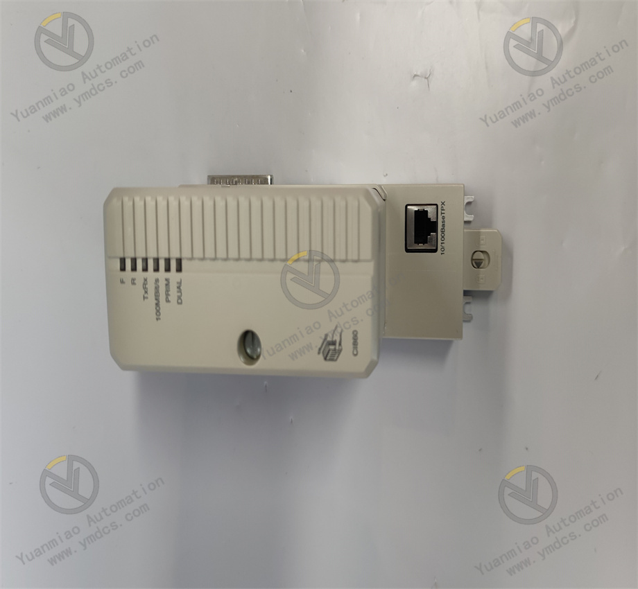
GE IS200VTURH2BAC
I. Product Overview
GE IS200VTURH2BAC is a core speed monitoring module in the Mark VIe series of industrial control systems. It is specifically designed for scenarios involving precise speed measurement and overspeed protection of key rotating mechanical equipment, such as gas turbines, steam turbines, water turbines, centrifugal compressors, fans, and pumps. As a core sensing unit for monitoring the operating status of rotating equipment, this module undertakes core functions including real-time collection of speed signals, high-precision calculation, overspeed alarm triggering, and data upload. It can be directly connected to front-end sensing devices like magnetoelectric speed sensors, photoelectric speed sensors, and Hall effect sensors to accurately capture changes in equipment speed, providing highly reliable data support for equipment start-stop control, working condition adjustment, overspeed protection, and preventive maintenance.
Based on the unified modular architecture design of the Mark VIe system, this module is compatible with controller series such as IC698CPU310. It supports hot-swap replacement and redundant configuration, enabling maintenance and upgrades without shutting down the system, thus significantly improving the continuity of equipment operation. It features industrial-grade anti-interference capability and wide environmental adaptability, having passed the IEC 61000 series electromagnetic compatibility certification and rigorous environmental reliability tests. It can operate stably in high-temperature, high-humidity, and strong-interference industrial scenarios such as electric power, petrochemicals, metallurgy, and rail transit, and serves as a core monitoring and protection component to ensure the safe and stable operation of key rotating equipment.
II. Functional Features
Multi-Channel High-Precision Speed Collection: The module integrates 4 independent speed collection channels. Each channel can be flexibly configured with collection modes via software according to the type of front-end sensor (magnetoelectric, photoelectric, Hall effect). It supports a wide range of speed measurement, covering 0.1r/min to 60000r/min. Equipped with a 16-bit high-precision counter and an adaptive sampling algorithm, the speed measurement accuracy reaches ±0.01%FS, enabling accurate capture of speed changes throughout the entire process of equipment from start-up, acceleration, rated operation to shutdown. It is particularly suitable for precise monitoring of high-speed rotating equipment. Each channel supports custom configuration of parameters such as the number of gear teeth and pulse count, adapting to speed measuring gears or pulse generators of different specifications.
Multi-Level Signal Conditioning and Anti-Interference Design: It adopts a three-level signal conditioning architecture of "Sensor Level - Channel Level - Module Level". Each channel has a built-in low-noise preamplifier, programmable threshold comparator, and wide-band filter network. The preamplifier can amplify the weak pulse signal (mV level) output by the sensor to a standard range. The programmable threshold comparator supports adjustable thresholds from 50mV to 5V, adapting to sensors of different sensitivities. The filter network supports high-pass (1Hz-100Hz), low-pass (1kHz-10kHz), and notch filtering (50Hz/60Hz power frequency suppression), which can accurately filter electromagnetic interference and mechanical vibration noise in industrial sites. The module adopts an overall photoelectric isolation design, with an isolation voltage of 2500V DC between channels and 1500V DC between the module and the system bus. Its anti-interference capability complies with the IEC 61000-4-2/3/4 standards.
Flexible Overspeed Protection and Alarm Mechanism: It supports a five-level speed protection mechanism (Normal, Early Warning, Alarm, Overspeed 1, Overspeed 2). Each channel can be independently configured with speed thresholds, hysteresis values, and response times for each level, with a threshold setting accuracy of 0.1r/min. Among them, "Overspeed 1" and "Overspeed 2" are high-priority protection thresholds. When triggered, they can directly output hard-wired trip signals (2 independent dry contact outputs) with a response time of ≤1ms, meeting the strict requirements for emergency shutdown of rotating equipment in case of overspeed. When the "Early Warning" and "Alarm" thresholds are triggered, alarm signals are output via communication protocols and LED indicators. When an alarm is triggered, the module automatically records information such as the speed value at the time of the alarm, the triggered threshold, and the equipment operation duration, providing a complete data chain for fault tracing. It supports an alarm suppression function, allowing the setting of alarm shielding time (adjustable from 0 to 600s) for special working conditions such as equipment start-up and shutdown to avoid false alarms.
Redundant Configuration and Hot-Swap Capability: It supports the dual-machine hot-standby redundant configuration of the Mark VIe system. The module can be connected to the redundant I/O network as a master/slave node. The speed data synchronization delay between the master and slave modules is ≤1ms. When the master module fails, the slave module can seamlessly take over the work to ensure uninterrupted speed monitoring and protection functions. It adopts a standardized guide rail installation structure and supports live hot-swap operation. The built-in contact protection circuit during plugging and unplugging can prevent arc generation, avoiding damage to the module and front-end sensors. The hot-swap replacement time is ≤30 seconds, greatly shortening maintenance downtime.
Real-Time Data Processing and Trend Analysis: Equipped with a high-performance microprocessor, it supports real-time speed calculation, historical trend recording, and statistical analysis functions. It can calculate key parameters such as average speed, maximum speed, minimum speed, and speed fluctuation in real time. Trend analysis can record historical speed change curves, supporting adjustable sampling periods from 1 second to 24 hours, with a data storage capacity of 8GB, which can meet the needs of historical data tracing for more than 1 year. It supports speed fluctuation over-limit detection, allowing custom setting of fluctuation thresholds (adjustable from 0.1% to 10%). When the speed fluctuation exceeds the threshold, an alarm is automatically triggered to promptly detect abnormal working conditions such as equipment rotor unbalance and load fluctuation.
- Convenient System Integration and Remote Operation & Maintenance: It supports GE's dedicated Genius Bus communication protocol and the standard Modbus TCP/IP protocol, and is equipped with 2 RJ45 Ethernet redundant communication interfaces with a communication rate of 100Mbps. It can be seamlessly connected to the Mark VIe control system and third-party SCADA platforms (such as GE Proficy iFIX, Wonderware Intouch). Through the GE Proficy Machine Edition software, remote parameter configuration (channel type, sensor parameters, alarm thresholds, etc.), firmware upgrade, and fault diagnosis of the module can be realized. It supports remote query and export of speed trend curves and alarm logs, eliminating the need for on-site connection of debugging equipment and improving operation and maintenance efficiency.
III. Technical Parameters
| Parameter Category | Parameter Name | Specific Parameters | Unit |
|---|---|---|---|
| Basic Parameters | Model | GE IS200VTURH2BAC | - |
| Product Type | Speed Monitoring Module | - | |
| Overall Dimensions (L×W×H) | 160×80×120 | mm | |
| Weight | Approximately 0.85 | kg | |
| Acquisition Performance Parameters | Number of Channels | 4 channels, independent isolation | Channel |
| Supported Sensor Types | Magnetoelectric speed sensor, photoelectric speed sensor, Hall effect sensor | - | |
| Measurement Range | 0.1r/min~60000r/min | r/min | |
| Measurement Accuracy | ±0.01%FS | - | |
| Sampling Frequency | 1kHz, independent sampling per channel | kHz | |
| Counter Accuracy | 16-bit | Bit | |
| Adaptable Number of Gear Teeth | 1~1000 teeth, software adjustable | Tooth | |
| Signal Processing Parameters | Filtering Methods | High-pass (1Hz-100Hz), low-pass (1kHz-10kHz), notch (50Hz/60Hz) | - |
| Threshold Adjustment Range | 50mV~5V, programmable and adjustable | mV/V | |
| Speed Fluctuation Detection Range | 0.1%-10%, software adjustable | % | |
| Real-Time Calculation Parameters | Average value, maximum value, minimum value, fluctuation value | - | |
| Alarm and Storage Parameters | Alarm Levels | 5 levels (Normal, Early Warning, Alarm, Overspeed 1, Overspeed 2) | - |
| Alarm Output | 2 dry contacts (overspeed protection), rated at AC 250V/5A; 2 status outputs, rated at DC 24V/1A | V/A | |
| Data Storage Capacity | 8GB, supporting cyclic coverage of historical data | GB | |
| Trend Sampling Period | 1 second-24 hours, adjustable | - | |
| Power and Communication Parameters | Power Supply Voltage | DC 24V±10%, supporting redundant power supply | V DC |
| Operating Current | ≤100mA at no load; ≤400mA at full load | mA | |
| Communication Interfaces | 2 RJ45 Ethernet ports (redundant) | - | |
| Supported Communication Protocols | Genius Bus, Modbus TCP/IP | - | |
| Environmental and Reliability Parameters | Operating Temperature Range | -40~70 | ℃ |
| Storage Temperature Range | -40~85 | ℃ | |
| Relative Humidity | 5%-95% (no condensation) | % | |
| Protection Level | IP20 (panel) | - | |
| Mean Time Between Failures (MTBF) | ≥200,000 | Hour |
IV. Working Principle
The working principle of the GE IS200VTURH2BAC speed monitoring module revolves around the core link of "signal collection - conditioning processing - speed calculation - protection judgment - data interaction". Combined with redundant protection and fault diagnosis mechanisms, it realizes high-precision monitoring and overspeed protection of the speed of key rotating equipment. The specific process is as follows:
- Redundant Power Supply and System Initialization:The module is connected to a DC 24V redundant power supply. After rectification, filtering, and voltage stabilization through the built-in power management circuit, a stable DC voltage is output to power the internal CPU, counter, signal conditioning circuit, isolation circuit, and other units of the module. The power management circuit monitors the status of the two input power supplies in real time. When one power supply fails (voltage lower than 21.6V or higher than 26.4V), it immediately switches to the other power supply, with a switching time of ≤1ms to ensure continuous operation of the module. After the module is powered on, it executes the initialization program to self-check the status of the CPU, counter, communication interface, and channel circuit. After initialization, the system status is fed back through the front-end LED indicators. In case of a fault, the corresponding fault code is output and uploaded to the controller.
- Speed Signal Collection and Conditioning:The front-end sensor (magnetoelectric/photoelectric/Hall effect) converts the mechanical speed of the rotating equipment into a pulse electrical signal, which is connected to the 4 independent collection channels of the module. Each channel has a built-in three-level signal conditioning unit: the low-noise preamplifier amplifies the mV-level weak pulse signal to a standard voltage range (0-5V); the programmable threshold comparator sets a threshold (adjustable from 50mV to 5V) according to the sensor type and sensitivity, converting the analog pulse signal into a digital pulse signal; the filter network filters interference signals according to preset parameters, such as suppressing 50Hz/60Hz power frequency interference through notch filtering and filtering high-frequency noise through low-pass filtering. The conditioned digital pulse signal is sent to the counter after being isolated by the photoelectric isolator, realizing electrical isolation between the on-site side and the internal circuit of the module, with an isolation voltage of 2500V DC.
- Speed Calculation and Data Processing:The isolated digital pulse signal is sent to a 16-bit high-precision counter, which counts the pulse signal at a sampling frequency of 1kHz. Based on the preset number of gear teeth (or pulse count) and counting time, the CPU calculates the real-time speed value using an adaptive algorithm. The formula is: Speed (r/min) = (Number of Pulses × 60) / (Number of Gear Teeth × Counting Time). At the same time, the CPU calculates the average speed, maximum speed, minimum speed, and fluctuation value in real time, where the fluctuation value = (Maximum Value - Minimum Value) / Average Value × 100%. The calculated speed data is used for real-time display and alarm judgment on the one hand, and stored in the 8GB memory according to a preset sampling period (adjustable from 1 second to 24 hours) to form a historical trend curve on the other hand.
- Protection Judgment and Alarm Output:The CPU compares the calculated real-time speed value with the preset five-level protection thresholds (Normal, Early Warning, Alarm, Overspeed 1, Overspeed 2) in real time. When the speed is within the "Normal" range, only the real-time data is updated; when it reaches the "Early Warning" threshold, the early warning indicator of the corresponding channel is lit and early warning information is uploaded via communication; when it reaches the "Alarm" threshold, the alarm indicator is lit, alarm information is uploaded via communication, and status output is triggered; when it reaches the "Overspeed 1" threshold, the first dry contact trip signal is triggered immediately (response time ≤1ms), and overspeed alarm information is uploaded at the same time; when it reaches the "Overspeed 2" threshold, the second dry contact trip signal is triggered to achieve dual overspeed protection. When an alarm is triggered, the module automatically records information such as the speed value at the time of the alarm, the triggered threshold, counting time, and equipment operation duration, stores timestamp information, and provides a complete data chain for fault tracing. It supports an alarm suppression function, which automatically shields alarms during special working conditions such as equipment start-up and shutdown, with an adjustable suppression time of 0-600s.
- Data Communication and System Collaboration:The module establishes a connection with the Mark VIe controller through a dual-network port redundant communication link, and performs data interaction using the Genius Bus or Modbus TCP/IP protocol. The CPU encapsulates real-time speed parameters (instantaneous value, average value, fluctuation value), alarm information, fault logs, and equipment status data into data packets, and uploads them to the controller and upper monitoring system through the main communication network port; at the same time, it receives configuration commands (channel type, sensor parameters, alarm thresholds, sampling period, etc.) issued by the controller and executes parameter updates. When the main communication network port fails, it automatically switches to the backup network port, with a switching time of ≤50ms to ensure uninterrupted data transmission. Historical speed trend curves and alarm logs can be called remotely through upper software for offline analysis and fault diagnosis.
- Fault Diagnosis and Self-Protection:The module has a built-in comprehensive fault diagnosis circuit that monitors the following fault types in real time: sensor faults (open circuit, short circuit, weak signal), channel circuit faults (amplifier failure, abnormal comparator), counter faults, CPU calculation faults, abnormal power supply voltage, communication interruption, etc. When a fault occurs, the CPU immediately implements protection measures: when a sensor fault occurs, the corresponding channel is automatically isolated without affecting the operation of other channels; when a fault occurs in the overspeed protection circuit, a fault alarm is triggered and the trip output is locked to avoid misoperation or failure to operate. At the same time, the CPU records the fault information (fault type, occurrence time, channel number), stores it in non-volatile memory (not lost when power is off), and uploads it to the controller through the communication link to facilitate quick location and handling by operation and maintenance personnel.
V. Common Fault Handling
| Fault Phenomenon | Possible Causes | Handling Measures |
|---|---|---|
| Power indicator not on, module unresponsive | 1. Both redundant power supplies are interrupted; 2. Loose or reversed power connection; 3. Fault in the internal power management circuit of the module | 1. Check the power supply switch and restore normal power supply; 2. Re-tighten the power connection and check the polarity of the positive and negative electrodes; 3. Replace the module and send the faulty module for repair |
| Abnormal speed measurement value of a channel (too large/too small/large fluctuation) | 1. Loose, damaged, or poorly grounded sensor cable; 2. Sensor fault (sensitivity drift, aging); 3. Improper gap between sensor and speed measuring gear; 4. Improper setting of channel filter parameters; 5. Fault in the module channel circuit | 1. Check and re-tighten the cable, replace the damaged cable, and ensure reliable grounding of the shielding layer; 2. Use a calibrator to test the sensor performance and replace the aging sensor in a timely manner; 3. Adjust the gap between the sensor and the speed measuring gear to the standard range; 4. Adjust the filter parameters (such as increasing the filtering depth) to filter interference signals; 5. Replace the module or repair the channel circuit |
| Trip protection not triggered during overspeed | 1. Overspeed protection threshold set too high; 2. Weak or lost sensor signal; 3. Loose or short-circuited dry contact output cable; 4. Fault in the module protection circuit | 1. Check the rated speed of the equipment and readjust the overspeed protection threshold; 2. Check the sensor installation and cable connection to ensure normal signal; 3. Check and re-tighten the dry contact cable to eliminate short-circuit faults; 4. Simulate an overspeed signal with a calibrator to test the protection function, and replace the module if faulty |