Description
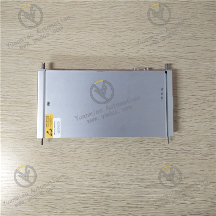
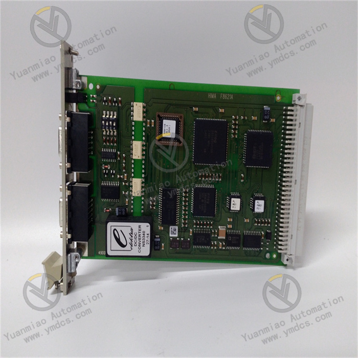
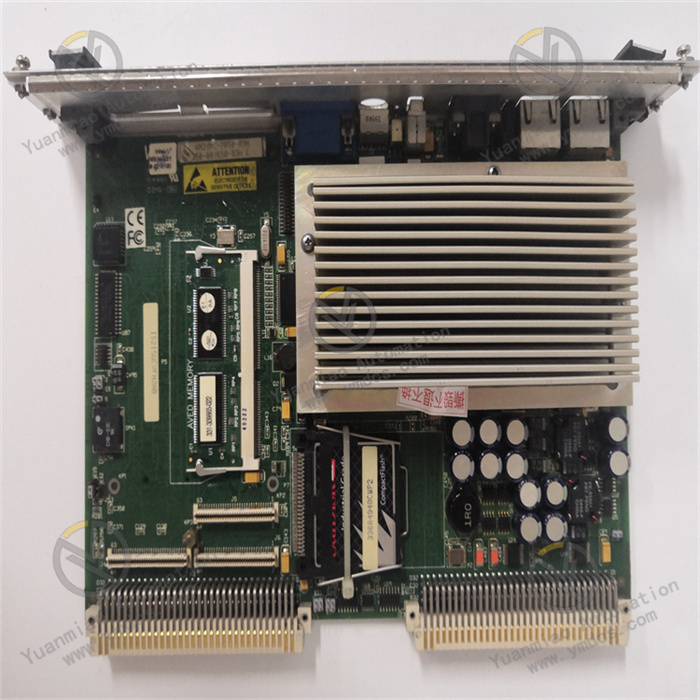
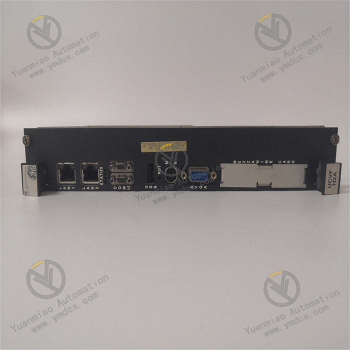
GE IS215UCVFH2BB
I. Overview
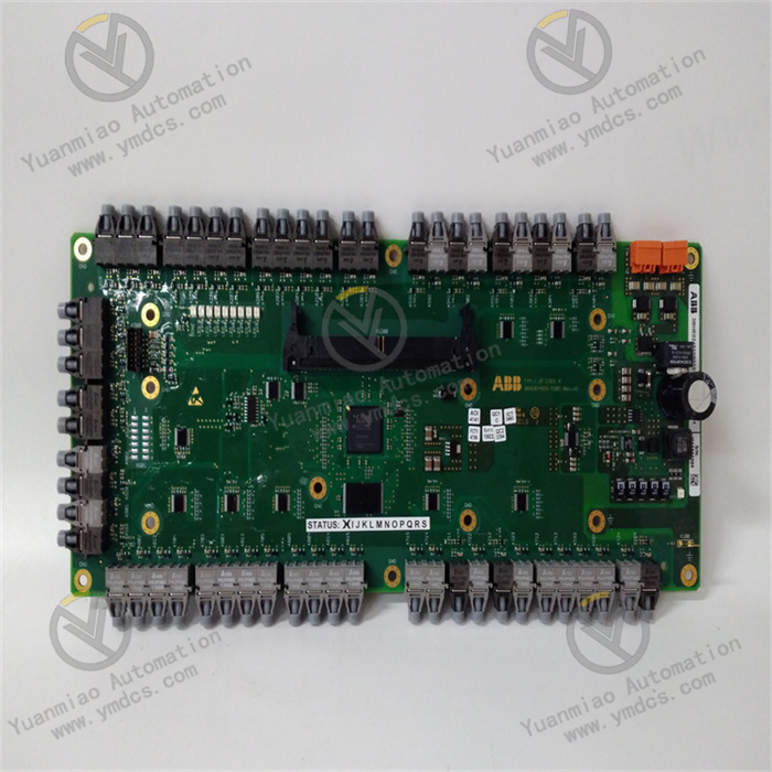
GE IS215UCVFH2BB is an industrial-grade control module, a core execution unit of the Mark VIe series control system, specifically designed for the precise control needs of medium and large industrial process control and complex equipment clusters. This module adopts a modular hardware architecture and redundant design concept, deeply integrating multi-channel high-precision signal acquisition, multi-core parallel computing, multi-type control output, and all-round anti-interference technology. It can realize real-time monitoring of multi-dimensional key parameters such as temperature, pressure, flow, liquid level, and speed in industrial sites, as well as rapid response control of actuators and dynamic feedback of system operation status.
II. Functional Features
GE IS215UCVFH2BB is deeply suitable for the complex needs of medium and large industrial control scenarios, integrating GE's cutting-edge technical accumulation in the field of industrial automation, and has the following core functional features:
- Multi-channel high-precision signal acquisition: Equipped with 8 high-precision analog input channels, supporting 4-20mA DC standard current signals, 0-10V DC standard voltage signals, K-type/E-type thermocouple temperature signals, and RTD (platinum resistance) temperature signal acquisition. The analog acquisition accuracy reaches ±0.05% FS, and the sampling refresh rate is increased to 200Hz, which can accurately capture subtle fluctuations of process parameters and provide high-fidelity data support for control decisions. At the same time, it is configured with 16 digital input channels (24V DC) for collecting discrete signals such as limit switches, travel switches, solenoid valve feedback, emergency stop signals, and equipment operating status. The input circuit adopts a 3000V AC photoelectric isolation design and is equipped with a surge suppressor (±2kV), which can effectively resist strong electromagnetic interference, pulse shocks, and power grid fluctuations in industrial sites, ensuring the stability and accuracy of discrete signal acquisition.
- Multi-type flexible control output: Has 6 configurable analog output channels, supporting 4-20mA DC/0-10V DC dual-mode output switching. The output accuracy reaches ±0.1% FS, and the load driving capacity is increased to 1000Ω, which can directly drive large valve positioners, high-precision actuators, high-voltage frequency converters and other control components, realizing micron-level precise adjustment of process parameters. Equipped with 12 digital output channels, using relay + transistor dual-mode output design (relay output capacity 5A/250V AC, transistor output capacity 2A/24V DC), supporting software configuration to set normally open/normally closed, pulse output, delay output and other modes, which can meet complex discrete control needs such as start-stop control of large equipment, sequence control of multiple sets of solenoid valves, and hierarchical output of alarm signals. The output circuit has a built-in triple protection mechanism against overcurrent, short circuit, and overvoltage. When abnormal load is detected, the output circuit can be quickly cut off and locked within 3ms. After the fault is eliminated, the output can be restored through software reset or local hard reset, effectively protecting the safety of the module and controlled equipment.
- Multi-core efficient computing and complex logic configuration: Equipped with a GE customized dual-core 32-bit industrial-grade MCU with a core operating frequency of 500MHz, combined with a floating-point arithmetic coprocessor, it has efficient instruction execution capability and complex algorithm processing capability. It can stably run various advanced control algorithms such as PID (Proportional-Integral-Derivative), PID cascade control, feedforward control, and fuzzy control, and support parallel computing of multi-variable coupling control logic. The module has a built-in 2MB program storage space and 8MB data storage space, which can store 16 sets of control logic schemes under different working conditions, supporting millisecond-level online mode switching according to the needs of production process switching, greatly improving the scenario adaptability of the system. Control logic development is carried out through GE ToolboxST advanced configuration software, using drag-and-drop function blocks + structured text programming dual modes, with built-in rich function block libraries such as flow accumulation, temperature compensation, interlock logic, fault diagnosis, and trend analysis. It supports visual modeling and offline simulation verification of complex control logic, significantly reducing development difficulty and on-site debugging risks.
- High-reliability communication and global system integration: Adopts Dual Genius Bus + Ethernet/IP dual communication architecture, equipped with 4 communication ports (2 Genius Bus + 2 Ethernet/IP), all supporting redundant configuration. The maximum communication rate of Genius Bus is 1Mbps, and the maximum communication rate of Ethernet/IP is 1Gbps, ensuring the real-time and reliability of data transmission between the module and the main controller, other control modules, and upper monitoring systems. It can be directly connected to the Mark VIe distributed control system to realize bidirectional high-speed data interaction with the main controller, IO modules, and fieldbus devices, upload real-time operating parameters, fault information, and diagnostic data, and receive control commands, parameter settings, and logic update commands issued by the main controller. At the same time, it supports compatibility with mainstream industrial communication protocols such as Modbus TCP/RTU, PROFINET, and EtherCAT through protocol conversion modules, meeting the global integration needs of third-party PLCs, SCADA systems, MES manufacturing execution systems, and cloud monitoring platforms, and realizing centralized monitoring, data traceability, and remote operation and maintenance of the production process.
- Comprehensive fault diagnosis and multi-level redundancy protection: Built-in advanced self-diagnosis module, adopting hardware + software dual diagnosis mechanism, real-time monitoring of key parameters such as the module's power supply status, communication link integrity, input and output channel signal quality, core circuit temperature, MCU operating status, and redundant module synchronization status. It supports accurate identification of faults such as sensor faults, actuator faults, line disconnections, and signal drifts. When an abnormality is detected, it can trigger a hierarchical alarm within 5ms, upload detailed information including fault code, fault location, fault level, and fault trend through the communication interface, and at the same time light up the corresponding LED fault indicator on the front of the module (with colors distinguishing fault levels), and trigger on-site sound and light alarms through relay output contacts, providing accurate guidance for maintenance personnel to quickly locate fault points. It supports module-level + channel-level dual hot redundancy configuration. The main and standby modules realize microsecond-level synchronization of collected data, control logic, and operating status through a dedicated high-speed synchronization interface. When the main module fails, the standby module can automatically and seamlessly switch to the working state within 10ms; key input and output channels support redundant configuration, and can automatically switch to the standby channel when a single channel fails, ensuring uninterrupted control processes and greatly improving the reliability and continuity of system operation.
- Industrial-grade robust and reliable design: Uses wide temperature range industrial-grade components, with an operating temperature range of -40℃~85℃ and a storage temperature range of -55℃~100℃, which can adapt to extreme environments such as high-temperature metallurgical workshops, low-temperature storage control systems, and outdoor open-air equipment. The module adopts a compact modular circuit layout, combined with an integrated high-efficiency heat dissipation module (including heat sink + cooling fan, supporting intelligent temperature control start and stop), which can achieve efficient heat dissipation of core components, ensuring that the module's temperature is stably controlled within 60℃ during full-load operation. The shell is made of high-strength flame-retardant aluminum alloy material, with an IP30 protection level, excellent vibration resistance (5-1000Hz, 2g acceleration) and impact resistance (20g, 11ms). It passes IEC 61000-6-2/4 industrial electromagnetic compatibility standards, UL safety certification, and ATEX explosion-proof certification (optional), with a mean time between failures (MTBF) of more than 200,000 hours.
- Intelligent configuration and full-life cycle operation and maintenance: Supports full-process operations such as module parameter configuration, control logic programming, fault diagnosis, data monitoring, trend analysis, and firmware upgrade through GE ToolboxST advanced configuration software. The software has a built-in advanced offline simulation function, which can simulate the operation effect of control logic under different working conditions, support fault injection testing, and verify the fault tolerance of the system in advance. The front of the module is equipped with a 2.4-inch color LCD display and 6 custom operation buttons, which can locally display parameters of each input and output channel, module operating status, redundancy status, fault information, and process curves in real time. It supports local parameter fine-tuning, control mode switching, fault reset, and logic scheme calling through the buttons. It supports online debugging, parameter modification, and firmware upgrade, and can complete configuration updates without disconnecting the system power supply. It is equipped with a USB data export interface, which can quickly export operation logs, fault records, and trend data, providing data support for the full-life cycle management of equipment, greatly improving operation and maintenance efficiency, and reducing equipment downtime.
III. Technical Parameters
| Parameter Category | Parameter Name | Specific Parameters | Unit |
|---|---|---|---|
| Basic Parameters | Model | GE IS215UCVFH2BB | - |
| Overall Dimensions (L×W×H) | 220×160×80 | mm | |
| Weight | Approximately 1.8 | kg | |
| Installation Method | Rack-mounted (compatible with GE Mark VIe standard cabinets and industrial standard 19-inch cabinets) | - | |
| Power Supply Parameters | Power Supply Voltage | DC 24V (±15%) / AC 220V (±10%) dual power input, automatic switching | V |
| Rated Power Supply Current | DC 24V: 5A; AC 220V: 1A | A | |
| Power Consumption | ≤80W (full load operation) | W | |
| Power Supply Redundancy | Supports redundant switching of dual independent power input, switching time ≤1ms | - | |
| Input/Output Parameters | Analog Input Channels | 8 channels, 4-20mA DC/0-10V DC/K-type/E-type thermocouple/RTD, ±0.05% FS accuracy | Channel |
| Digital Input Channels | 16 channels, 24V DC, 3000V AC photoelectric isolation, ±2kV surge suppression | Channel | |
| Analog Output Channels | 6 configurable channels, 4-20mA DC/0-10V DC, ±0.1% FS accuracy, 1000Ω load | Channel | |
| Digital Output Channels | 12 channels, relay (5A/250V AC) + transistor (2A/24V DC) dual-mode output | Channel | |
| Isolation Voltage | 3000V AC (mutual isolation between input/output/power supply/communication) | V | |
| Sampling Refresh Rate | 200Hz (analog input), 0.5ms (digital input) | Hz/ms | |
| Output Response Time | ≤1ms (analog output), ≤0.1ms (digital output) | ms | |
| Communication & Reliability Parameters | Communication Interfaces | 2 Genius Bus + 2 Ethernet/IP, all supporting redundant configuration | Port |
| Communication Rate | Genius Bus: up to 1Mbps; Ethernet/IP: up to 1Gbps | bps | |
| Operating Temperature Range | -40~85 | ℃ | |
| Storage Temperature Range | -55~100 | ℃ | |
| Relative Humidity | 5%~95% (no condensation) | % | |
| Mean Time Between Failures (MTBF) | ≥200,000 | Hour |
IV. Working Principle
GE IS215UCVFH2BB realizes precise control of medium and large industrial equipment and complex processes based on the closed-loop control process of "multi-source signal acquisition - multi-core parallel processing - complex logic operation - precise command output - global communication interaction - multi-level fault protection". Its specific working principle is as follows:
- Multi-source signal acquisition link:Various sensor signals in the industrial field (such as 4-20mA signals output by pressure sensors, K-type thermocouple signals for temperature monitoring, 0-10V signals output by flow sensors, 24V DC signals output by limit switches) are connected to the corresponding input channels of the module through special shielded cables. The analog input channel has a built-in high-precision signal conditioning circuit, which performs filtering, amplification, linearization, and temperature drift compensation on the input analog signal. For thermocouple signals, cold junction compensation is automatically performed; for RTD signals, a three-wire acquisition method is used to eliminate the influence of lead resistance, effectively eliminating errors caused by on-site electromagnetic interference, temperature drift, line resistance, and other factors. The conditioned analog signal is converted into a digital signal through a 24-bit high-precision A/D converter, completing the high-fidelity digital conversion of the analog quantity. The discrete signals connected to the digital input channel first undergo dual protection through a photoelectric isolation circuit + surge suppression circuit to prevent external strong interference signals from entering the module. Then, the signal is shaped by a Schmitt trigger to ensure that the input digital signal has clear edges and no jitter, ensuring the integrity and reliability of the discrete signal.
- The collected digital signals (including digital signals converted from analog quantities and shaped digital signals) are transmitted to the dual-core control unit (MCU) through the high-speed data bus (with a rate of 100Mbps) inside the module, completing the signal acquisition and transmission process. Among them, the analog acquisition delay is ≤3ms, and the digital response time is ≤0.5ms, which can meet the strict requirements for data real-time performance in medium and large industrial control scenarios; key input channels support redundant configuration, and the collected data is subject to real-time consistency verification to ensure data accuracy.
- Multi-core parallel processing and complex logic operation link:After receiving the collected digital signals, the dual-core MCU performs parallel processing in a division of labor and cooperation mode: Core 1 is responsible for data calibration, scaling conversion, and data preprocessing, converting the original digital signals into corresponding actual physical quantities (for example, converting 4-20mA current signals into pressure values of 0-20MPa, converting thermocouple digital signals into temperature values of 0-1000℃), and performing filtering, outlier removal, and trend prediction on the data; Core 2 is responsible for control logic operations, and according to the advanced control logic preset through GE ToolboxST configuration software (such as PID cascade control logic, multi-variable coupling control logic, equipment interlock protection logic, fault diagnosis logic, etc.), combined with real-time collected physical parameters, preset control target values, and historical operating data, performs comprehensive calculations to generate precise control commands. For example, in the temperature control scenario of a chemical reactor, the MCU generates analog commands to adjust the power of the heating device and analog commands to adjust the opening of the cooling water valve simultaneously through cascade PID operation based on real-time data of the temperature inside the reactor (main variable) and the flow rate of cooling water in the jacket (secondary variable), realizing precise temperature control; when it detects that the gas turbine speed exceeds the safety threshold, it immediately generates digital commands for emergency shutdown, control commands to cut off fuel supply, and hierarchical alarm signals.
- While performing data processing and logic operations, the MCU simultaneously runs hardware + software dual self-diagnosis programs, real-time monitoring key parameters such as the module's power supply voltage, communication link signal strength, signal status of each input and output channel, core circuit temperature, working status of A/D/D/A converters, synchronization status of redundant modules, and its own operating status, and compares them with the preset normal threshold range. If an abnormal parameter is detected (such as power supply voltage exceeding ±15% range, communication link interruption, excessive channel signal drift, abnormal redundant synchronization), fault information is immediately generated, marking the fault type, fault location, fault level, and fault trend data.
- Precise control command output link:The control commands generated by the dual-core MCU are divided into analog control commands and digital control commands according to their types, which are transmitted to the corresponding output channels respectively. The analog control command is first converted into a 4-20mA/0-10V standard analog signal through a 24-bit D/A converter, then amplified by a power drive circuit and output to the controlled actuator (such as a large valve positioner, high-precision actuator, high-voltage frequency converter). The precise control of process parameters is realized by adjusting the action of the actuator; the output signal is collected in real-time feedback and compared with the command signal to ensure the accuracy of the output. The digital control command drives the relay or transistor to act according to the configuration mode, outputting the corresponding switch signal to the controlled equipment (such as feed pump, alarm light, solenoid valve, emergency shut-off valve), realizing discrete control functions such as equipment start-stop control, sequence control, and alarm signal output; the relay output channel supports contact status feedback to real-time monitor the validity of the output status.
- The output channel has a built-in triple protection circuit against overcurrent, short circuit, and overvoltage, which real-time monitors the current and voltage status of the output circuit. When an overcurrent (relay output exceeds 5A, transistor output exceeds 2A), short circuit, or overvoltage fault is detected in the output circuit, the protection circuit acts immediately to quickly cut off the output circuit and lock the output state. At the same time, the fault information is fed back to the core MCU, and the fault handling logic is triggered through software (such as switching to the standby output channel, triggering redundant module switching) to avoid the fault expansion causing damage to the module or controlled equipment; after the fault is eliminated, the output function can be restored only through GE ToolboxST configuration software or the module's local hard reset button.
- Global communication interaction and data synchronization link:The module establishes a stable high-speed communication link with the Mark VIe main controller, upper monitoring system, and other control modules through the Dual Genius Bus + Ethernet/IP dual communication architecture. It uploads real-time operating parameters, fault information, diagnostic data, redundancy status, and trend data to the main controller according to the preset communication cycle (configurable 1-10ms), and simultaneously receives control commands, parameter settings, logic update commands, and remote operation and maintenance commands issued by the main controller; through the Ethernet/IP interface, it interacts with the upper SCADA system and MES system, supporting real-time upload of production data and issuance of remote control commands, realizing centralized monitoring and remote operation and maintenance of the production process. The communication link supports redundant configuration. When the main communication link fails, the standby communication link can automatically switch within 1ms to ensure communication continuity; communication data adopts CRC check + encrypted transmission to prevent loss and tampering during data transmission.
- When the module adopts redundant configuration, the main and standby modules establish a real-time data synchronization link through a dedicated high-speed synchronization interface (with a rate of 1Gbps). The main module synchronizes the collected data, calculated control commands, operating status, and diagnostic information to the standby module in real-time to ensure data consistency and status consistency between the main and standby modules. The main module sends a heartbeat signal to the standby module every 0.5ms, and the standby module real-time monitors the heartbeat status and operating status of the main module, providing an accurate basis for redundant switching.
- Multi-level fault handling and redundant switching link:When a minor fault is detected (such as signal drift, transient communication interruption), the module automatically executes fault self-healing logic (such as recalibrating the channel, switching the communication link), and uploads fault early warning information through the communication interface without affecting the normal control process; when a serious fault is detected (such as main MCU fault, power failure, key channel fault), it immediately triggers a hierarchical protection mechanism: first, lock the current control state through the output channel to avoid misoperation of the controlled equipment; then, if it is a module-level fault, the standby module detects the main module's fault information within 10ms, immediately triggers the redundant switching mechanism, automatically switches to the working state, takes over all control tasks and communication tasks of the main module, ensuring uninterrupted control processes; if it is a channel-level fault, automatically switches to the standby channel to maintain control accuracy. The faulty main module or channel automatically enters an isolated state to avoid affecting other parts of the system.
- After the module detects a fault, while uploading the fault information to the main controller and upper system, it lights up the indicator corresponding to the fault type through the LED fault indicator on the front of the module (red/yellow/green to distinguish fault levels), displays the fault code, fault location, fault cause, fault level, and handling suggestions on the 2.4-inch color LCD display, and triggers on-site sound and light alarms through relay output contacts; the fault information is stored in non-volatile memory in real-time, supporting data retention after power failure. Maintenance personnel can query fault details through the LCD display or upper software to quickly locate the fault point.
V. Common Faults and Solutions
| Fault Phenomenon | Fault Code | Possible Causes | Troubleshooting Methods | Precautions |
|---|---|---|---|---|
| No response after module power-on, power indicator not on | ERR-PWR-001 | 1. Both power supplies are not connected, or power cable connections are loose/fallen off; 2. Power supply voltage exceeds the rated range of DC 24V±15%/AC 220V±10%; 3. Faulty internal power module of the module; 4. Blown fuse in the power circuit; 5. Faulty power switching circuit | 1. Check if both power supply switches are closed, check if the connection between the power cable and module terminals is firm, re-plug and fasten the connections; 2. Use a multimeter to measure the voltage of both power supplies, ensure the voltage is within the rated range, and adjust the power supply if the voltage is abnormal; 3. Connect the two power supplies separately, observe the module's response, if there is no response, contact GE after-sales technicians to inspect the power module; 4. Remove the module housing (special tools required), replace the fuse with the same specification (10A/250V AC); 5. Diagnose the power switching circuit through GE ToolboxST software, replace the power switching module if necessary | Before replacing the fuse, check for short-circuit points in the power circuit to avoid re-fusing; removing the module housing must be done by professionals to prevent damage to internal circuits; dual power supplies must be connected to independent power circuits to ensure effective power redundancy; do not force single-circuit operation when the power switching circuit is faulty, and repair it in time |
| Excessive deviation or frequent fluctuations in analog input data | ERR-AI-002 | 1. Loose connections, poor contact, or damaged shielded cables between the sensor and the module; 2. Faulty sensor causing abnormal output signals; 3. Input cables not using twisted-pair shielded wires or shield not grounded at one end (ground resistance ≤4Ω), subject to strong external electromagnetic interference; 4. Lost or drifted calibration parameters of the module's analog input channel; 5. Strong electromagnetic interference sources on-site (such as high-power frequency converters, high-voltage motors) without shielding measures; 6. Inconsistent data in redundant input channels | 1. Check the connection terminals between the sensor and the module, fasten loose connections, replace damaged shielded cables; 2. Disconnect the sensor from the module, input the corresponding signal to the module using a high-precision standard signal source, replace the sensor if the data is normal; 3. Replace with twisted-pair shielded wires, ensure the shield is grounded at one end with a ground resistance ≤4Ω; 4. Re-calibrate the analog input channel through GE ToolboxST configuration software, using a standard signal source for multi-point calibration; 5. Keep input cables away from strong interference sources, shield the cables with pipes, or add signal isolators at the module input end; 6. Check the wiring of redundant input channels, re-calibrate the dual channels to ensure data consistency | Calibration requires a standard signal source with accuracy ≥0.01%; thermocouple calibration requires a standard temperature source, RTD calibration requires a standard resistance box; the shield is prohibited from being grounded at multiple points to avoid introducing interference due to ground loops; redundant channels must undergo consistency verification after calibration |
| Communication interruption, module cannot interact with main controller or upper system | ERR-COM-003 | 1. Damaged communication cables, wrong wiring, or loose terminals; 2. Mismatched communication parameters (such as address, baud rate, protocol type) between the module and the main controller; 3. Damaged communication interface; 4. Both communication links fail; 5. Faulty protocol conversion module (in third-party system integration scenarios); 6. Missing or damaged terminating resistors for the communication bus | 1. Replace with dedicated communication cables, verify the wiring pin definitions (refer to the module communication manual), fasten communication terminals; 2. Check the module's communication parameters through GE ToolboxST configuration software, ensure they are consistent with the main controller's parameters, restart the module for the changes to take effect; 3. Switch to the standby communication interface, contact GE after-sales to repair the communication interface if communication still fails; 4. Test the dual communication links separately, repair the faulty link; 5. Check the power supply and configuration of the protocol conversion module, restart or replace the module if necessary; 6. Check the communication bus terminating resistors (120Ω for Genius Bus, 50Ω for Ethernet/IP), replace if damaged | Communication parameters take effect after module restart; Genius Bus must have matching resistors at terminal nodes; Ethernet/IP communication must ensure IP addresses are in the same network segment without conflicts; communication cables must be kept away from power cables to avoid electromagnetic interference; faulty redundant communication links must be repaired in time to avoid single-point failure |
| No analog output signal or excessive deviation between output value and set value | ERR-AO-004 | 1. Loose, broken output cables, or poor contact at terminals; 2. Faulty controlled actuator or load resistance exceeding 1000Ω; 3. Output channel locked due to overcurrent, short circuit, or overvoltage protection; 4. Faulty module D/A converter; 5. Abnormal output commands due to incorrect control logic configuration; 6. Faulty output signal feedback loop | 1. Fasten output terminals, replace broken cables; 2. Disconnect the actuator, measure the module's output signal with a high-precision multimeter, repair or replace the actuator if the signal is normal, ensure the load resistance is within 1000Ω; 3. Troubleshoot and eliminate the causes of short circuit, overcurrent, or overvoltage in the output loop, reset the module through GE ToolboxST software or local hard reset button; 4. Contact GE after-sales technicians to inspect the D/A converter; 5. Check the control logic through GE ToolboxST configuration software, correct configuration errors and perform offline simulation verification; 6. Check the wiring of the output signal feedback loop, re-calibrate the feedback channel | Use a multimeter with accuracy ≥0.02% when measuring output signals, disconnect the controlled load to avoid load affecting measurement accuracy; the load resistance of the actuator must not exceed 1000Ω, add a power amplifier if it exceeds; do not reset the module before eliminating short circuit/overcurrent/overvoltage faults; suspend relevant control processes when the output feedback loop is faulty to avoid miscontrol |
| In redundant configuration, standby module cannot switch automatically after main module failure | ERR-Red-005 | 1. Redundant synchronization cable between main and standby modules is not connected or loose; 2. Incorrect redundant parameter configuration (such as address conflict between main and standby modules, unreasonable synchronization cycle setting); 3. Standby module is not powered on or has its own faults; 4. Inconsistent firmware versions of main and standby modules; 5. Incorrect configuration of redundant switching logic; 6. Damaged synchronization interface | 1. Check the connection of the redundant synchronization cable, ensure the plug is tight and terminals are fastened; 2. Check redundant parameters through GE ToolboxST configuration software, correct the addresses of main and standby modules and synchronization cycle (it is recommended to set to 1ms), ensure parameters are consistent; 3. Check the power supply status and operating status of the standby module, troubleshoot and eliminate its own faults; 4. Upgrade the firmware of main and standby modules to the same latest version (must be done when the equipment is shut down); 5. Reconfigure the redundant switching logic, enable automatic switching mode and perform fault injection tests; 6. Replace the redundant synchronization interface module, contact GE after-sales for repair if necessary | Firmware upgrade must be done when the equipment is shut down, back up configuration parameters and control logic before upgrading; main and standby modules must be of the same model and batch, mixing different models is prohibited; redundant parameters must be synchronized to main and standby modules and take effect after restart; redundant switching logic must undergo multiple fault injection tests to verify switching reliability; synchronization cables must use dedicated shielded cables to avoid interference with synchronization signals |