Description
Technical Parameters:
Input/Output: Supports up to 32 digital input channels and 32 digital output channels, each of which can be individually programmed. It supports up to 16 analog input channels and 8 analog output channels. The input/output range of analog signals typically includes -10VDC to +10VDC, 0-20mA, or 4-20mA.
Communication Protocols: Supports communication protocols such as Ethernet and Modbus TCP/IP, facilitating seamless integration with other system components or devices.
Environmental Adaptability: Specifically designed for harsh industrial environments, it has a wide operating temperature range and can withstand shocks and vibrations.
Diagnostic Functions: Equipped with built-in diagnostic and self-test functions to ensure module reliability and quickly detect faults or errors in the system.
Programming and Customization: Can be programmed using GE's proprietary programming languages (such as C) and supports customized control strategies and algorithms.
Fiber Optic Interfaces: Typically features multiple fiber optic interfaces that support high-speed data transmission to meet transmission requirements in different application scenarios.
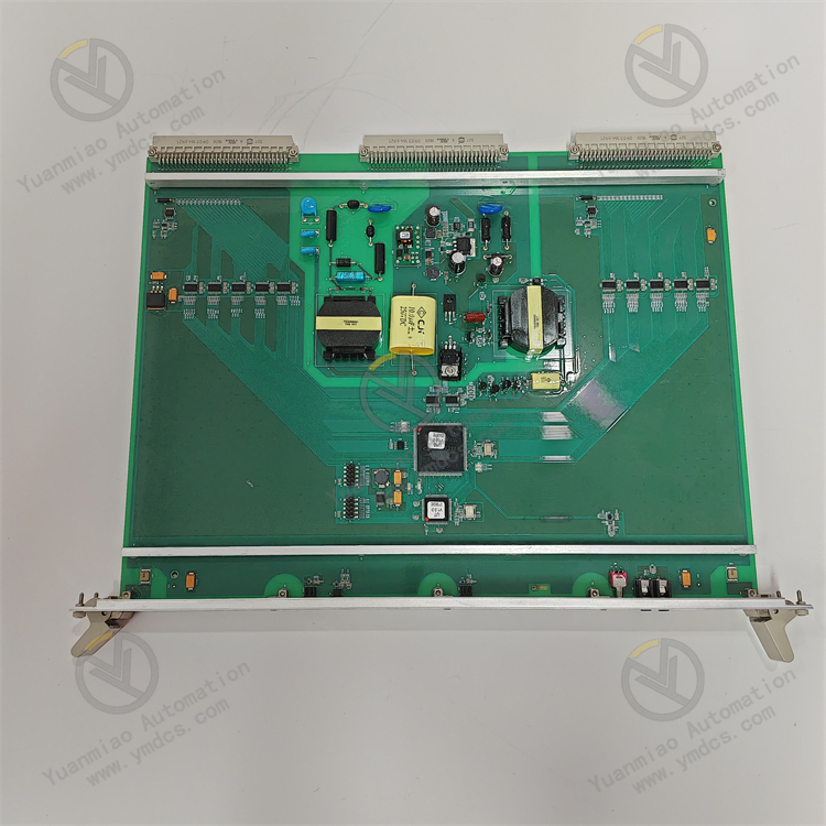
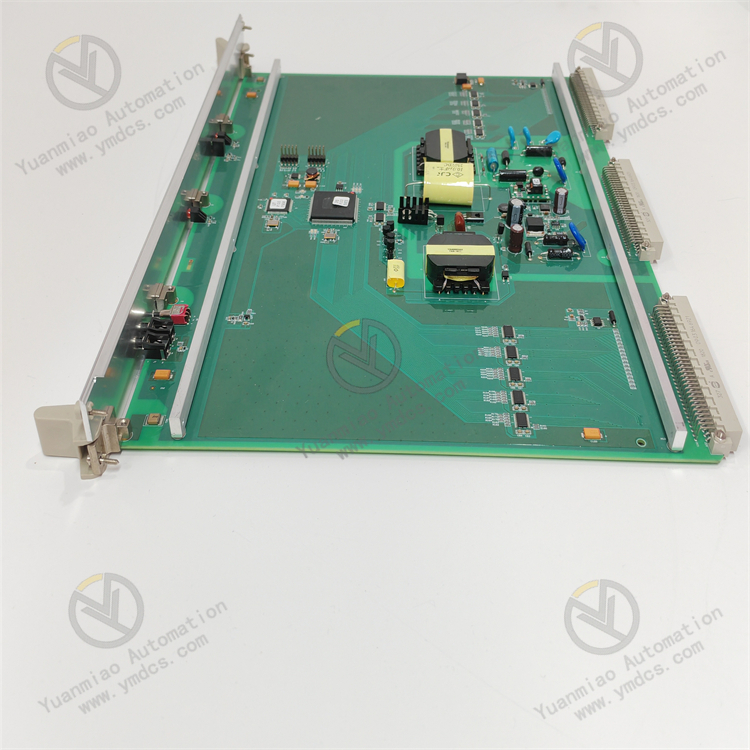
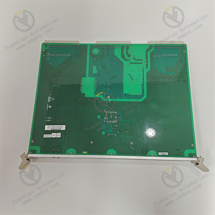
Hot Swap Function: Supports hot swapping, enabling maintenance and replacement without affecting system operation.
Input/Output: Supports up to 32 digital input channels and 32 digital output channels, each of which can be individually programmed. It supports up to 16 analog input channels and 8 analog output channels. The input/output range of analog signals typically includes -10VDC to +10VDC, 0-20mA, or 4-20mA.
Communication Protocols: Supports communication protocols such as Ethernet and Modbus TCP/IP, facilitating seamless integration with other system components or devices.
Environmental Adaptability: Specifically designed for harsh industrial environments, it has a wide operating temperature range and can withstand shocks and vibrations.
Diagnostic Functions: Equipped with built-in diagnostic and self-test functions to ensure module reliability and quickly detect faults or errors in the system.
Programming and Customization: Can be programmed using GE's proprietary programming languages (such as C) and supports customized control strategies and algorithms.
Fiber Optic Interfaces: Typically features multiple fiber optic interfaces that support high-speed data transmission to meet transmission requirements in different application scenarios.
Hot Swap Function: Supports hot swapping, enabling maintenance and replacement without affecting system operation.
Functional Features:
I. High Reliability and Industrial-Grade Design
Adaptability to Harsh Environments
- Constructed with a rugged metal casing, it meets industrial-grade protection standards (e.g., IP20 and above). It can withstand a wide temperature range of -20°C to 70°C, vibrations (e.g., compliant with IEC 60068-2-6 standards), and dust pollution, suitable for harsh scenarios such as workshops, railways, and energy sectors.
- The power supply features surge and reverse polarity protection, supporting a wide voltage input of 24V DC±10% to ensure stable operation during power grid fluctuations.
High Availability Architecture
- Supports hot swapping, allowing module replacement without system shutdown and reducing production downtime risks.
- Built-in hardware watchdog and self-test mechanisms continuously monitor device status and automatically recover from minor faults (e.g., transient communication interruptions), reducing maintenance costs.
II. Flexible Input/Output (I/O) Configuration
Abundant I/O Channels
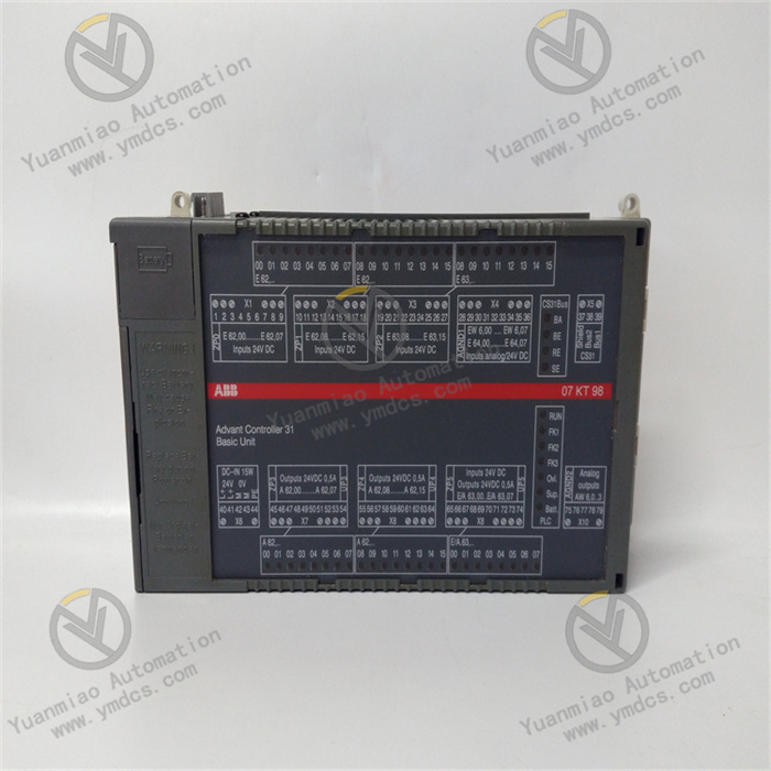
- May be equipped with 32 digital input (DI) + 32 digital output (DO) channels, supporting dry/wet contact inputs, with output types optional relay or transistor (adaptable to different load requirements).
- 16 analog input (AI) + 8 analog output (AO) channels, compatible with voltage (e.g., 0-10V) and current (e.g., 4-20mA) signals, with a resolution of 12 bits or higher to meet high-precision data acquisition needs.
Scalability and Modularity
- Supports bus expansion modules (e.g., Ethernet or proprietary buses) to flexibly adapt to I/O point expansion requirements in complex systems.
- Channels support independent programming; for example, digital inputs can be configured for edge triggering or pulse counting, and analog inputs can set filter parameters or open-circuit detection.
III. Efficient Communication and System Integration
Multi-Protocol Communication Capability
- Standard Ethernet interface (Modbus TCP/IP) supports real-time data interaction with PLCs, SCADA systems (e.g., Alstom's TX8000 series), or cloud platforms, with transmission rates up to 10/100Mbps.
- Compatible with industrial bus protocols such as Modbus RTU (RS485) and CANopen, facilitating integration with legacy devices or third-party sensors/actuators.
Fiber Optic Communication Expansion (Optional)
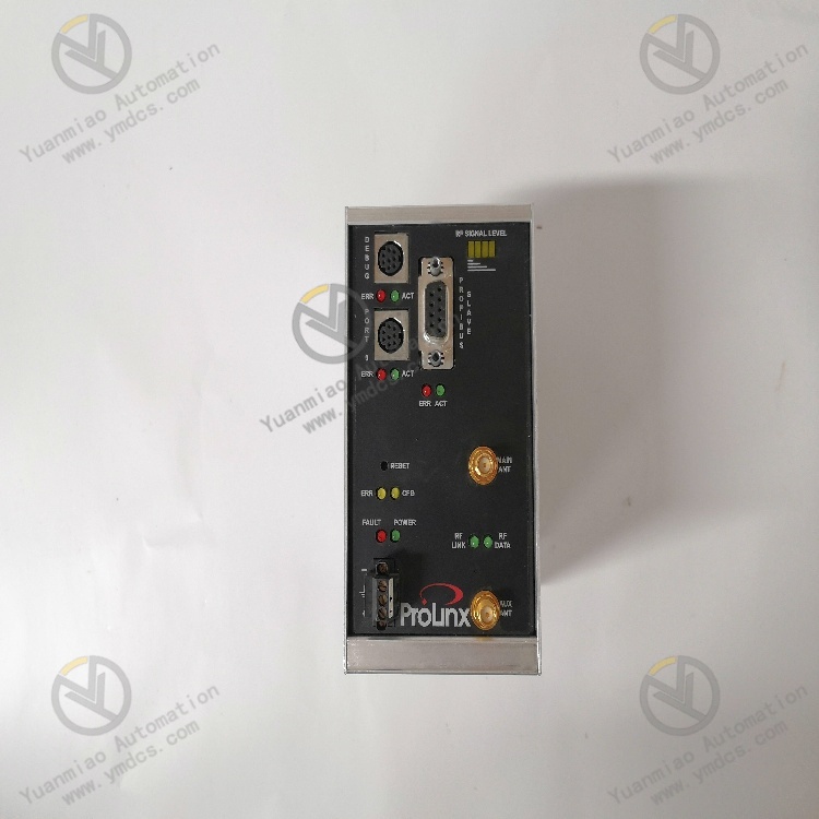
- May be equipped with fiber optic interfaces (e.g., ST/SC ports), supporting long-distance (kilometer-level) high-speed data transmission with strong anti-electromagnetic interference capabilities, suitable for high-reliability scenarios such as rail transit and power systems.
IV. Intelligent Control and Diagnosis
Programmable Logic Control (PLC) Functions
- Built-in microprocessor supports custom control logic development using IEC 61131-3 standard programming languages (e.g., Ladder Diagram LD, Structured Text ST) to achieve local real-time control (e.g., motor start/stop, valve adjustment).
- Supports floating-point operations and complex algorithms, enabling advanced functions such as PID control, data filtering, and status monitoring.
Real-Time Diagnosis and Alarming
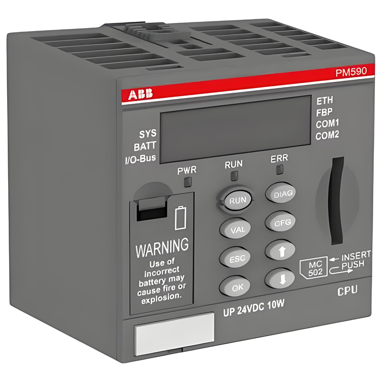
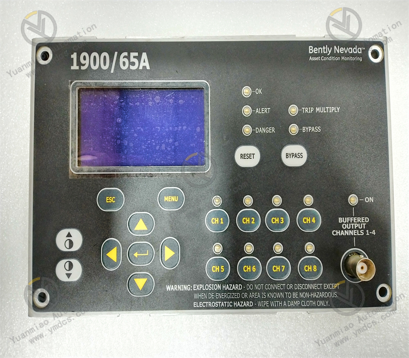
- Panel-mounted LED indicators (e.g., power, operation, communication, fault) visually display device status.
- Supports real-time monitoring of I/O status, voltage/current values, temperature, and other parameters via host computer software (e.g., Alstom Control Suite), with alarm pop-ups and email notifications (e.g., communication interruptions, out-of-threshold values).
- Built-in fault log storage function records over 500 recent events for quick problem localization.
V. Energy Efficiency and User Friendliness
Low-Power Design
- Static power consumption below 10W, with dynamic power consumption varying with I/O load, compliant with industrial energy efficiency standards to reduce long-term operating costs.
Convenient Operation and Maintenance
- Supports local button or LCD menu configuration (e.g., IP address, baud rate), allowing basic parameter setup without additional tools.
- Host computer software provides a graphical interface supporting batch import/export of parameters and online firmware upgrades, streamlining large-scale deployment and maintenance processes.
VI. Typical Application Scenarios
- Manufacturing: Logic control for automated production lines, equipment status monitoring, and quality inspection data acquisition.
- Rail Transit: Train traction system control, signal system I/O expansion, and on-board equipment status monitoring.
- Energy and Power: Substation relay protection interfaces, data acquisition for photovoltaic/wind inverters, and energy storage system control.
- Logistics and Warehousing: AGV scheduling logic, conveyor belt start/stop control, and warehouse environmental sensor integration.
Operation Key Points
Installation:
- Physical Installation: May need to be mounted on a DIN rail, ensuring secure fixation and easy layout in control cabinets or equipment racks. Leave sufficient space for heat dissipation and future maintenance during installation.
- Electrical Connections: When connecting power, verify that the input voltage meets device requirements (typically specified as 24V DC, etc.), ensuring correct polarity. For Ethernet-supported communication, connect to an industrial switch or host computer via a network cable and configure network parameters such as IP address. For Modbus RTU, use an RS485 interface, paying attention to terminating resistor configuration and matching communication parameters (baud rate, parity) with the host computer.
Parameter Configuration:
- Local Configuration: May be set via the device's built-in display and button menu, e.g., configuring communication parameters (Ethernet IP address, subnet mask, gateway) or Modbus slave address and baud rate. May also include configuring functional parameters (e.g., data acquisition frequency, control logic thresholds) based on specific application scenarios.
- Remote Configuration: Use Alstom's dedicated configuration tools or general Modbus debugging tools to establish a communication connection (Ethernet or serial) with the device, then import or manually configure parameter templates and download them to complete initialization.
Operation and Monitoring:
- Startup: Before powering on, check that all connections are secure and free of short circuits or looseness. After closing the power switch, the device will perform a self-test. Wait for the self-test to complete and the device to enter normal operation, then check readiness via indicators or the display.
- Status Monitoring: During operation, real-time data such as I/O values, operating temperature, and communication status can be viewed via the local interface or host computer software. In case of faults (e.g., communication interruptions, voltage anomalies), the device will notify operators via indicator flashes, interface pop-ups, or host computer alarms.
Maintenance and Troubleshooting:
- Routine Maintenance: Regularly clean the device with a dry soft cloth to prevent dust accumulation affecting heat dissipation. Periodically inspect wiring terminals for looseness, retighten as needed, and clean oxidation layers. Perform functional tests to verify data acquisition, control logic, and communication functions.
- Fault Troubleshooting: When a fault occurs, analyze possible causes based on symptoms and take corresponding actions. For example, if there is no power indication, check the power switch or replace the fuse. If communication is interrupted, replace the network cable or reconfigure communication parameters.