Description
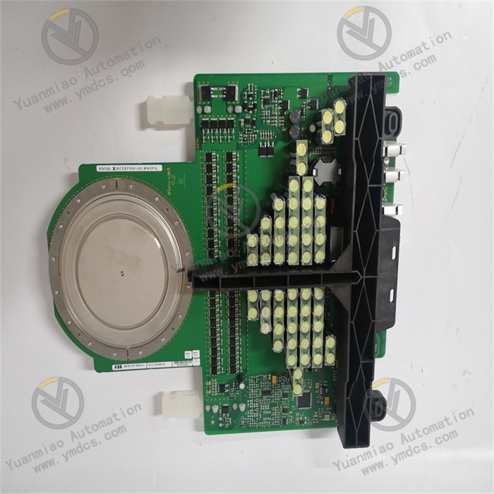
GE VMIVME-7750
I. Overview
GE VMIVME-7750 is a dedicated VME bus processor module for industrial control systems. Designed based on a 32-bit RISC processor and the VMEbus standard architecture, it primarily undertakes three core functions: "high-performance computing data processing - multi-bus protocol conversion - real-time control task scheduling". It is highly compatible with VME bus-based industrial control systems and can serve as a main controller to connect VME series I/O modules (such as the VMIVME-3122 analog input module and VMIVME-3310 digital output module). Meanwhile, through extended interfaces, it connects to external networks like Ethernet and RS485, enabling full-link collaboration of "underlying device data collection - local computing processing - upper-layer monitoring interaction". It is widely used in scenarios such as steam turbine control, radar signal processing, and large-scale industrial equipment cluster management and control.
Compared with ordinary VME processor modules, this product has three core advantages:
- High computing power and real-time performance: It adopts a high-performance RISC processor and a real-time operating system, meeting the requirements of multi-task parallel scheduling and millisecond-level control response;
- Multi-protocol compatibility: It integrates multiple types of interfaces including VMEbus, Ethernet, and Serial, and supports Modbus, TCP/IP, and VMEbus slave protocols to realize cross-bus data interaction;
- Industrial-grade reliability: It features a wide-temperature design, redundant power supply support, and enhanced anti-interference capabilities, making it suitable for harsh industrial environments (such as high temperatures and strong electromagnetic interference) with a Mean Time Between Failures (MTBF) of over 200,000 hours.
II. Technical Parameters
1. Basic Specifications
| Item | Parameter Details |
|---|---|
| Equipment Type | VME Bus 3U Processor Module (Single-board Computer) |
| Bus Standard | Compatible with VMEbus IEEE 1014 Standard (32-bit data bus, 4GB address space) |
| Installation Method | 3U VME Standard Rack Slot Installation (occupies 1 x 3U slot) |
| Overall Dimensions | 3U VME Standard Size (100mm×160mm×25mm, compatible with VME cabinet layout) |
| Protection Class | IP20 (Installed in rack, protection against solid foreign objects) |
| Operating Temperature Range | -40°C ~ 70°C (wide-temperature operation, suitable for high and low-temperature industrial scenarios); -55°C ~ 85°C (storage) |
| Power Supply Requirement | +5V DC (1.5A rated), ±12V DC (0.5A rated), supporting redundant power supply input |
2. Hardware Parameters
Processor and Storage Architecture
- CPU Configuration: 32-bit RISC processor (such as Motorola PowerPC series or equivalent architecture) with a clock frequency of 266MHz ~ 400MHz, supporting a Floating-Point Unit (FPU). Its single-instruction-cycle computing capability is ≥100 MIPS, meeting the real-time execution requirements of complex control algorithms (such as PID regulation and filtering operations);
- Storage Capacity:
- Program Storage: 16MB ~ 64MB Flash Memory, supporting power-off preservation of firmware and control programs, and remote upgrade via Ethernet;
- Data Storage: 64MB ~ 256MB SDRAM (with ECC error checking function), reducing the error rate of memory data and ensuring computing reliability;
- Expanded Storage: Supports 1 x CompactFlash (CF) card interface (maximum 1GB) for storing fault logs, configuration files, and offline data;
- Real-Time Clock (RTC): Built-in RTC with battery backup, capable of maintaining time recording for ≥7 days after power-off, ensuring the accuracy of fault log timestamps.
Interface and Communication Characteristics
| Interface Type | Specification Parameters | Function Purpose |
|---|---|---|
| VMEbus Interface | 32-bit data/address bus, supporting Master/Slave modes, transmission rate ≤40MB/s | Connects to VME bus I/O modules (such as analog and digital modules) to realize data interaction between modules and issuance of control commands |
| Ethernet Interface | 1 x 10/100Base-TX RJ45 interface, supporting TCP/IP and UDP protocols | Connects to upper-layer SCADA systems, HMIs, or remote monitoring terminals to realize data upload and remote configuration |
| Serial Interface | 2 x switchable RS232/RS485 serial ports (maximum baud rate 115200bps), supporting Modbus RTU protocol | Connects to on-site serial devices such as sensors and frequency converters, or serves as a debugging terminal interface |
| Dedicated Control Interface | 1 x VMEbus Interrupt Request (IRQ) interface, 1 x System Reset (RESET) interface | Receives interrupt signals from I/O modules (such as fault alarms) to realize emergency task scheduling; resets the module locally/remotely |
| Debug Interface | 1 x JTAG debug interface, supporting hardware-level program debugging and fault diagnosis | Program debugging during the development phase and underlying fault location during the operation and maintenance phase |
Anti-Interference and Environmental Adaptability
- Electromagnetic Compatibility: Radiation emission complies with EN 55022 Class B standard; immunity complies with EN 61000-6-2 standard (electrostatic discharge ±8kV contact/±15kV air, electrical fast transient ±2kV, surge ±4kV);
- Power Supply Anti-Interference: The power input end is equipped with a built-in EMI filter and Transient Voltage Suppressor (TVS) to resist power grid surges and voltage fluctuations (such as ±10% voltage deviation);
- Mechanical Stability: Vibration resistance complies with IEC 60068-2-6 standard (10-500Hz, acceleration 2g, duration 10min/axis); shock resistance complies with IEC 60068-2-27 standard (acceleration 15g, duration 11ms, 3 times per axis for 3 axes).
III. Functional Features
1. High Computing Power and Real-Time Control Capability
- Multi-Task Scheduling Optimization: Supports VxWorks or QNX Real-Time Operating System (RTOS), enabling simultaneous operation of multiple tasks such as "data collection", "control algorithm calculation", "fault diagnosis", and "communication interaction". Task priorities can be dynamically configured (e.g., the "emergency shutdown" task has the highest priority with a response time < 1ms), meeting the real-time requirements of industrial control (e.g., steam turbine speed regulation cycle ≤ 10ms);
- ECC Memory Protection: SDRAM has a built-in ECC error checking function, which can automatically detect and correct single-bit memory errors, avoiding abnormal control logic caused by memory data errors (such as equipment misoperation due to calculation deviations) and improving computing reliability;
- Hardware Acceleration Support: Some models integrate a dedicated Digital Signal Processing (DSP) coprocessor to accelerate signal processing tasks such as filtering and FFT (e.g., spectral analysis of vibration signals), reducing the load on the main CPU and ensuring the response speed of core control tasks.
2. Multi-Bus Collaboration and Protocol Compatibility
- VMEbus Master-Slave Dual Modes: In VMEbus Master mode, it can actively initiate read/write operations on VME I/O modules (e.g., reading analog data from VMIVME-3122); in Slave mode, it can receive commands from other VME master modules to realize collaborative control of multiple main controllers (e.g., dual-machine redundant backup);
- Cross-Network Data Conversion: Through Ethernet and serial interfaces, it realizes bidirectional conversion between VMEbus protocol and Modbus/TCP/IP protocols (e.g., converting analog data collected by VME I/O modules into TCP/IP protocol for upload to SCADA systems, or converting Modbus commands into VMEbus commands for issuance to I/O modules);
- Redundant Communication Support: The Ethernet interface supports link aggregation or dual-network redundancy configuration (requiring coordination with external switches). When one Ethernet path fails, it can automatically switch to the backup link (switching time < 100ms), ensuring uninterrupted communication with the upper-layer monitoring system.
3. Industrial-Grade Reliability Design
- Wide-Temperature and Harsh Environment Adaptation: The wide operating temperature range of -40°C ~ 70°C covers outdoor cabinets in cold regions (e.g., wind power control boxes in northern China) and areas near high-temperature equipment (e.g., beside metallurgical furnaces) without the need for additional temperature control equipment; the PCB adopts a conformal coating (moisture-proof and corrosion-proof), adapting to humid environments (5%-95% RH, no condensation) such as water vapor areas in power plants;
- Redundant Power Supply and Overcurrent Protection: Supports dual-channel ±5V/±12V DC redundant power supply input. When one power supply path fails, the other path switches without interruption (switching time < 1ms); the power circuit is equipped with a 2A self-recovering fuse to prevent burnout of internal circuits due to overcurrent;
- Fault Self-Detection: Built-in hardware-level fault detection circuit that can real-time monitor CPU operation status, memory integrity, and VMEbus communication status. When a fault is detected (e.g., memory error, bus timeout), it immediately triggers the on-board red fault indicator and sends fault codes (e.g., E01 = CPU abnormality, E05 = VMEbus communication fault) to external alarm devices via VMEbus or Ethernet.
4. Convenient Operation & Maintenance and Development Support
- Visual Status Indication: The front panel is equipped with 6 LED indicators — Power Light (green steady on = normal power supply), VMEbus Communication Light (yellow flashing = normal communication), Ethernet Light (blue flashing = normal network connection), Fault Light (red steady on = module fault), CF Card Light (orange steady on = card ready), Reset Light (white flashing = reset in progress). The module's operating status can be quickly determined without software;
- Flexible Development Interfaces: Supports C/C++ programming language and real-time operating system API development, and provides VMEbus driver libraries and communication protocol stacks (such as Modbus protocol library) to simplify control program development; the JTAG debug interface supports online debugging and program downloading, facilitating problem location during the development phase;
- Fault Log Storage: Supports storing fault information (including timestamp, fault type, and CPU load) in the CF card, with a maximum capacity of 1000 logs. Logs can be exported to TXT format via the CF card, facilitating maintenance personnel to trace the cause of faults (e.g., analyzing whether equipment shutdown is caused by module memory errors).
IV. Operation, Maintenance and Troubleshooting
Daily Maintenance Points
- Status Monitoring: Check the module's operating parameters (CPU load, memory usage, VMEbus communication rate) via HMI or SCADA system daily to ensure CPU load < 70%, memory usage < 80%, and no fault code alarms;
- Interface Inspection: Inspect the VMEbus slot connection (contact between the module and rack backplane) monthly. Reinsert the module to ensure clean and oxidation-free contacts (if there are oxidation marks on the contacts, wipe them with alcohol cotton); check the wiring of Ethernet and serial ports, and fasten screws to prevent loosening due to vibration;
- Storage and Firmware Maintenance: Back up the configuration files and fault logs in the CF card quarterly, format and update the CF card (industrial-grade CF cards such as SanDisk industrial cards are recommended); upgrade the module firmware (via Ethernet or CF card) according to GE's official technical announcements to fix known vulnerabilities;
- Environmental Control: Ensure the temperature inside the cabinet is within the range of -40°C ~ 70°C. Regularly clean the dust from the module's heat dissipation holes (blow along the heat dissipation direction with compressed air) to prevent CPU frequency reduction due to overheating (the surface temperature of the module during normal operation should be < 60°C).
Common Faults and Solutions
| Fault Phenomenon | Possible Causes | Solutions |
|---|---|---|
| Power light off, module unresponsive | 1. Power supply not connected or abnormal voltage (e.g., +5V missing); 2. Redundant power supply switching fault; 3. Burnt internal power circuit | 1. Use a multimeter to test the ±5V/±12V power supply voltage and confirm it is within the rated range (+5V±5%, ±12V±10%); 2. Disconnect one power supply path, test whether the backup power supply switches normally, and check the redundant power supply circuit if switching fails; 3. If the module remains unresponsive with normal power supply, replace it with a module of the same model (burnt internal power circuits are mostly irreversible) |
| VMEbus communication interruption (communication light not flashing) | 1. Poor contact of VME backplane; 2. Incorrect VMEbus address configuration of the module; 3. VMEbus fault (e.g., conflict with other modules) | 1. Pull out the module and reinsert it into the VME slot to ensure full contact of the contacts; clean the slot contacts with alcohol; 2. Reconfigure the module's VMEbus address (range 0-255) via DIP switches or software to avoid address conflict with other modules; 3. Disconnect other modules on the bus, connect them one by one to identify the conflicting module, and replace the faulty module |
| Ethernet communication failure (Ethernet light off) | 1. Loose or faulty network cable; 2. IP address conflict or incorrect gateway configuration; 3. Burnt Ethernet port | 1. Replace with a test network cable, reinsert the RJ45 interface; use a network cable tester to check the continuity of the cable; 2. Verify the module's IP address (avoid duplication with SCADA system devices) and confirm the subnet mask and gateway are consistent with the monitoring system; 3. Replace with a backup Ethernet port (if available) or send the port circuit back to the factory for repair |
| Fault light steady on (memory error reported) | 1. Damaged SDRAM memory; 2. Inactive ECC checking function; 3. Incorrect memory configuration parameters | 1. Restart the module to attempt recovery; if the fault persists, test memory integrity via the JTAG interface and replace the damaged memory chip; 2. Re-enable the ECC checking function in BIOS configuration; 3. Restore the module's factory memory configuration parameters (load the default configuration file via the CF card) |
| CF card unreadable (CF card light off) | 1. CF card not inserted tightly or damaged; 2. Poor contact of CF card interface; 3. Faulty CF card controller of the module | 1. Reinsert the CF card or replace it with a known normal industrial-grade CF card for testing; 2. Clean the CF card interface contacts with alcohol cotton; 3. If the card remains unreadable after replacement and cleaning, send the CF card controller back to the factory for repair |