Description
GE IS200EPSMG1ABB
I. Overview
As a key component of the Mark VIe series, this module has core advantages of "high-efficiency conversion - high reliability - modular adaptation":
- It adopts an industrial-grade switching power supply design, featuring high conversion efficiency and low energy loss;
- It uses military-grade components and is coated with a thick PCB protective layer, enabling it to withstand harsh environments such as high temperatures and vibrations in power plants;
- Its modular structure supports quick plug-and-play replacement and is highly compatible with the GE Speedtronic series turbine control systems (covering gas, steam, and wind turbines).
Compliant with international safety standards such as UL and equipped with comprehensive overvoltage and overcurrent protection mechanisms, it serves as the "power core" for ensuring the stable operation of the excitation systems of power generation equipment, and is widely used in core scenarios of the power industry including thermal power, hydropower, and wind power.
II. Technical Parameters
1. Basic Specifications
| Item | Parameter Details |
|---|---|
| Equipment Type | Mark VIe series excitation power module, used for voltage conversion and power supply in the excitation systems of power generation equipment |
| Compatible Systems | GE Mark VIe excitation control system, Speedtronic gas/steam/wind turbine management system, compatible with front-end components such as EPDM boards |
| Power Supply Standard | Complies with international industrial power supply safety standards, certified by UL, and adapted to the high-reliability power supply requirements of power plants |
| Installation Method | Mark VIe standard rack card-type installation; compact design to fit the limited space of control cabinets; supports hot-swap maintenance |
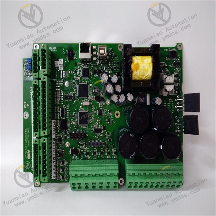
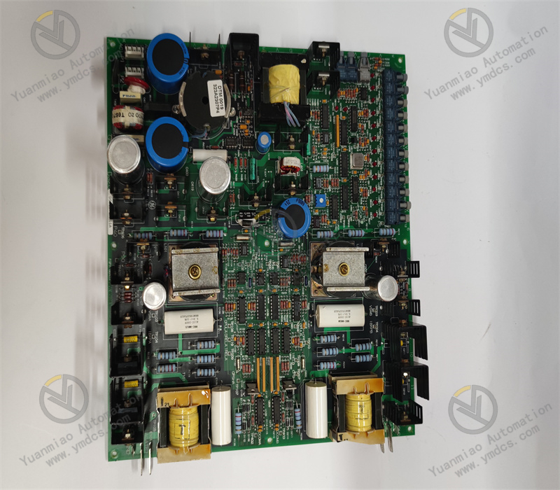
| Physical Features | The front panel integrates 7 status indicator lights (marked P5, P15, N15, P24A, P24B, N24B, P70), with GE logo and board number |
| Equipment Weight | Approximately 0.2-0.3 kg (industrial-grade lightweight design for easy installation and replacement) |
| Power Supply Requirements | Input voltage: 125V DC (from EPDM board); Input current: dynamically adjusted based on load configuration |
| Operating Environment | Temperature: -20°C~65°C (covering the temperature difference range between equipment in power plants); Humidity: 5%~95% (non-condensing) |
| Protection Design | PCB boards are coated with a thick protective layer, providing moisture and corrosion resistance; electrical isolation protection at input and output terminals |
| Storage Environment | Temperature: -40°C~85°C; Humidity: 5%~95% (non-condensing); supports long-term storage and transportation |
2. Performance Parameters
Voltage Conversion Characteristics
| Item | Parameter Details |
|---|---|
| Conversion Technology | Integrates a Buck-boost converter (for voltage step-up/step-down regulation) and a push-pull inverter (for generating high-frequency square-wave voltage) to ensure conversion efficiency and stability |
| Output Voltage Group | Standard outputs: +5V DC (for logic circuits), ±15V DC (for analog circuits), +24V DC (for drive/display circuits); supports multiple independent outputs |
| Conversion Efficiency | Industrial-grade high-efficiency design with a typical conversion efficiency of ≥90%, reducing energy loss and module heat generation |
| Output Stability | Output voltage ripple ≤50mV (at full load); voltage accuracy ±1% of rated value, ensuring stable operation of load equipment |
| Load Capacity | Maximum current per output channel: +5V DC output ≤10A, ±15V DC output ≤2A, +24V DC output ≤5A (compatible with multiple types of loads) |
Safety and Protection Characteristics
| Item | Parameter Details |
|---|---|
| Protection Functions | Equipped with overcurrent protection (automatic current limiting in case of short circuit), overvoltage protection (cutting off power supply when output is overvoltage), and undervoltage alarm (triggered when input voltage is lower than 100V DC) |
| Fault Response | Protection mechanism trigger time ≤100μs, quickly cutting off the fault circuit to prevent damage to the module and downstream load equipment |
| Isolation Capacity | Electrical isolation between input and output, with an isolation voltage of ≥2500V AC for 1 minute, blocking interference transmission |
| Redundancy Adaptation | Supports parallel redundancy configuration of two modules; automatically switches to the standby module when the main module fails to ensure continuous power supply |
Structural and Collaborative Characteristics
| Item | Parameter Details |
|---|---|
| Hardware Composition | Integrates core components such as a dedicated transformer and Bicron B9309 09-type large inductor to enhance power handling capacity |
| Communication Interface | Communicates with the system main controller via the Mark VIe backplane bus, and uploads real-time data such as output voltage, load current, and fault status |
| Collaboration Capacity | Highly compatible with GE excitation system components; can directly supply power to control modules, sensor drive circuits, and HMI display units without additional conversion equipment |
III. Functional Features
1. Precise Multi-Voltage Conversion, Adapting to Complex Loads of Excitation Systems
2. High Efficiency, Energy Saving, and Low Loss, Adapting to Long-Term Operation Requirements
3. Multi-Layer Protection Mechanism, Ensuring Safe and Reliable Power Supply
4. Modular Design and Status Visualization, Simplifying Operation and Maintenance Management
5. In-Depth System Collaboration, Adapting to Multiple Types of Power Generation Equipment
IV. Operation, Maintenance, and Troubleshooting
Daily Maintenance Points
- Status Monitoring: Check the module's output voltage values via the HMI system daily (ensure +5V DC is between 4.95-5.05V, ±15V DC is between ±14.85-±15.15V, and +24V DC is between 23.76-24.24V), inspect the status of the front indicator lights, and ensure no abnormal alarms. Pay special attention to the P70 main status light, which should be on to indicate the normal operation of the module.
- Physical Inspection: Conduct on-site inspections weekly to ensure the module is securely installed and the backplane bus connections are not loose. Use an infrared thermometer to measure the module's surface temperature, which should be <60°C to avoid performance degradation due to overheating. Clean dust from the module and the heat dissipation holes of the rack to maintain good ventilation.
- Regular Calibration: Calibrate the output voltage using a standard power calibrator every six months, and adjust the internal potentiometer to restore the output accuracy to within ±1%. Test the effectiveness of the protection functions (e.g., simulate an output short circuit to verify if the overcurrent protection is triggered).
- Redundancy Check: For modules in redundant configuration, confirm the synchronization status of the main and standby modules via the HMI monthly, ensuring the output voltage deviation between the standby module and the main module is <0.1V and the switching logic is normal.
Common Faults and Solutions
| Fault Phenomenon | Possible Causes | Solutions |
|---|---|---|
| A certain output voltage indicator light is off (e.g., P5 light is off) | 1. Fault in the corresponding output circuit; 2. Damaged internal converter; 3. Load overload | 1. Disconnect the load of this circuit; if the indicator light turns on, it indicates a load short circuit, and the load equipment should be repaired; 2. Measure the voltage at the module's output terminals; if there is no output, the internal converter is damaged, and the module needs to be replaced; 3. Check if the load current exceeds the rated value, and reduce the load or expand the capacity |
| All indicator lights are off, and the module has no output | 1. Interruption of 125V DC input; 2. Loose input wiring; 3. Damaged power circuit of the module | 1. Use a multimeter to measure the output voltage of the EPDM board and confirm that 125V DC is normal; 2. Re-tighten the input terminals to ensure good contact; 3. If there is still no response when the input is normal, replace the module |
| Frequent triggering of overvoltage protection | 1. Excessive fluctuation of input voltage; 2. Fault in the internal voltage regulation circuit | 1. Check the output stability of the EPDM board and install a voltage stabilizer if necessary; 2. If the measured output voltage continuously exceeds 10% of the rated value, it indicates a fault in the regulation circuit, and the module should be replaced |
| Redundancy switching failure | 1. Communication interruption between the main and standby modules; 2. Fault in the standby module; 3. Incorrect synchronization parameters | 1. Check the backplane bus connection and re-plug the modules; 2. Test the output of the standby module independently to confirm there is no fault; 3. Verify the synchronization parameters of the main and standby modules using GE configuration software and restore the default settings |
V. Application Scenarios
- Excitation System of Steam Turbines in Thermal Power Plants: In the excitation system of a 600MW steam turbine, the module serves as the core power supply, converting 125V DC into ±15V DC to supply the PID control circuit of the excitation regulator, +5V DC to supply the logic operation unit, and +24V DC to supply the thyristor trigger circuit. Its overcurrent protection function can quickly limit the current in case of a thyristor short circuit, preventing damage to the excitation winding and ensuring the stable power generation of the steam turbine.
Excitation Control of Gas Turbines: In the gas turbine system of a combined-cycle power plant, the module is adapted to high-vibration environments (with PCB coating and reinforced component design), providing a stable +24V DC power supply for the fuel injection control circuit and ±15V DC voltage for the signal conditioning circuit of the speed sensor, ensuring the gas turbine speed control accuracy is ±1rpm.
Excitation System of Hydro Turbines in Hydropower Plants: In the excitation system of a hydro turbine in a large hydropower plant, the module adopts a dual-redundancy configuration. When the main module fails, it switches to the standby module within 10ms to ensure the excitation current is not interrupted. Its wide-temperature design can adapt to the -20°C low-temperature environment of the outdoor control cabinet in the hydropower plant without additional heating devices.
Excitation System of Wind Turbines in Wind Farms: In the excitation system of a wind turbine, the module dynamically responds to changes in wind speed. When the wind speed suddenly increases from 10m/s to 15m/s, it quickly increases the +24V DC output current to 4A to drive the pitch motor and adjust the blade angle, preventing the turbine from overloading and adapting to the dynamic load requirements of wind power scenarios.