Description
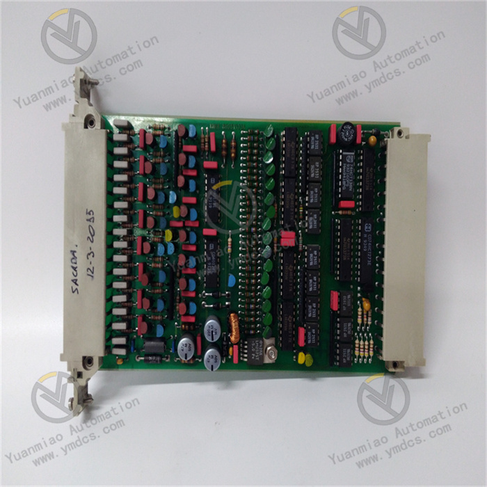
GE IS210AEBIH3BEC
I. Overview
The GE IS210AEBIH3BEC is a high-density digital input terminal board, with its core positioning as the "signal acquisition and preprocessing hub for Mark VIe/Mark VIeS series turbine and generator control systems". It mainly serves industries that have extremely high requirements for equipment status monitoring accuracy and signal reliability, including power generation (gas turbine/steam turbine control), petrochemicals (large-scale compressor/pump unit monitoring), and metallurgy (blast furnace fan/rolling mill drive control). It undertakes the key tasks of "centralized acquisition of multiple types of on-site digital signals, anti-interference preprocessing, and accurate transmission to the main controller".
II. Technical Specifications
(I) Core Signal Acquisition Parameters
Input Channels and Types
- Number of Channels: 32 independent digital input channels (divided into 4 groups, 8 channels per group, supporting group isolation). Compared with the 24-channel terminal board of the same series, the channel density is increased by 33%, which can reduce the number of terminal boards installed in the cabinet (e.g., originally 2 pieces of 24-channel terminal boards are needed, but now only 1 piece of 32-channel terminal board is required), saving 40% of cabinet space.
- Signal Type: Supports dual-mode input of dry contacts/wet contacts. Dry contacts are compatible with passive switches (e.g., mechanical limit switches), and wet contacts are compatible with active signals (e.g., 24V DC proximity sensors). The channel mode can be switched with one click through software without hardware modification.
Input Voltage Range:
- Wet contact mode: 24V DC (wide-range adaptation of 19V DC ~ 32V DC), 125V DC/AC (optional voltage module), compatible with sensors/switches with different on-site power supply specifications.
- Dry contact mode: Supports normally open/normally closed contacts, with contact operating current ≤ 1mA (low-power design to extend switch service life).
- Response Time: ≤ 0.5ms (time from signal triggering to completion of acquisition by the terminal board), supports edge detection (configurable rising edge/falling edge), avoiding false acquisition caused by signal jitter (e.g., contact jitter during motor start-stop).
Anti-Interference and Signal Processing Parameters
- Isolation Performance: Adopts "channel-level, group-level, power supply-level" three-level electrical isolation. The isolation voltage between channels is ≥ 500Vrms for 1 minute, between groups is ≥ 1000Vrms for 1 minute, and between power supply and signals is ≥ 2500Vrms for 1 minute. This effectively blocks ground loop interference (e.g., signal crosstalk caused by ground potential differences between different devices).
Electromagnetic Interference Resistance: Complies with EN 61000-6-2/EN 61000-6-4 industrial immunity standards. It has electrostatic discharge (ESD) protection of ±15kV (air discharge)/±8kV (contact discharge), radio frequency radiation immunity of 10V/m (80MHz ~ 1GHz), and burst immunity of ±2kV (5kHz). In strong interference environments such as high-voltage motors and frequency converters, the signal bit error rate is ≤ 10⁻⁹.
- Filtering Function: Built-in digital filtering (configurable filtering time of 0.1ms ~ 10ms) and hardware RC filtering (10kHz cutoff frequency). Dual filtering can eliminate high-frequency interference (e.g., signal glitches caused by electromagnetic radiation) and low-frequency jitter (e.g., contact bounce of mechanical switches), with a post-filtering signal stability of ≥ 99.9%.
Transmission and Synchronization Parameters
- Communication Interface: Connected to Mark VIe main controllers (e.g., IS200 series) through GE's dedicated backplane bus. The bus rate is ≥ 100Mbps, and the signal transmission delay is ≤ 1ms (from terminal board to main controller). It supports "clock synchronization" with the controller (synchronization error ≤ 10μs) to ensure the time consistency of signals collected by multiple terminal boards.
Data Buffer: Built-in 256KB data buffer, which can temporarily store 1000 pieces of signal status data (including timestamps). When the backplane bus is temporarily interrupted (≤ 500ms), data is not lost and will be automatically retransmitted after the bus is restored, avoiding data disconnection.
- Status Indication: Each channel is equipped with an independent LED indicator (steady green = signal "on", off = signal "off", blinking = signal abnormal). Group-level fault indicators are provided (steady red = fault in the group of channels), facilitating quick on-site troubleshooting.
(II) Physical and Environmental Parameters
Physical Specifications
- Dimensions: 220mm (length) × 150mm (width) × 50mm (height) (19-inch 3U rack-mounted, compatible with Mark VIe standard cabinets). Consistent with the size of terminal boards in the same series, it can directly replace the old 24-channel terminal board without modifying the cabinet mounting holes.
- Weight: Approximately 0.8kg. The lightweight design supports hot swapping by a single person (replacement time ≤ 2 minutes). When plugging and unplugging, the connection between the terminal board and the backplane bus is automatically disconnected without affecting the operation of other terminal boards.
- Terminal Blocks: Adopts spring-loaded quick-connect terminal blocks (compatible with 1.0mm² ~ 2.5mm² wires). No tools are needed for wiring (wires can be fixed by pressing), which improves wiring efficiency by 50% compared with screw terminals. Terminals are arranged in zones (power supply zone, channel zone, bus zone) with clear labels (e.g., "CH1-8", "PWR+") to avoid wiring errors.
Environmental Adaptability
- Operating Temperature: -40℃ ~ +70℃, meeting the operation requirements of extremely cold areas (e.g., outdoor substations in Northeast China) and high-temperature workshops (e.g., near rolling mills in metallurgical plants). No preheating is required for low-temperature startup (-40℃), and the startup time is ≤ 30s.
- Humidity: 5% ~ 95% (non-condensing, complying with IEC 60068-2-3 standard). In coastal high-humidity and high-salt-fog environments (e.g., offshore wind power platforms), the circuit board is coated with nano-scale three-proof paint (waterproof, dustproof, anti-corrosive), and the terminals are gold-plated to prevent corrosion and poor contact.
Protection Level: IP20 (installed inside the cabinet), compatible with industrial control cabinets with IP54 protection level, preventing dust and slight moisture intrusion.
- Vibration and Shock Resistance: Vibration resistance level of 10g (10Hz ~ 2000Hz, complying with IEC 60068-2-6), capable of withstanding continuous vibration during turbine operation (vibration acceleration ≤ 10g); shock resistance level of 20g (11ms pulse, complying with IEC 60068-2-27), capable of withstanding instantaneous shocks during equipment handling and maintenance.
(III) Power Supply and Reliability Parameters
- Power Supply Requirements: Adopts dual-channel redundant power input (24V DC, terminals marked "PWR1+", "PWR1-", "PWR2+", "PWR2-"). The input current of a single power channel is ≤ 200mA (in full configuration), and the power consumption is ≤ 4.8W. The dual power supplies automatically achieve load balancing; when one power supply fails, the other takes over within ≤ 100μs to ensure the continuous operation of the terminal board.
Reliability Indicators: Mean Time Between Failures (MTBF) ≥ 500,000 hours (Telcordia SR-332 standard, at 25℃), design life ≥ 15 years. Key components (e.g., optocouplers, filter capacitors) are selected with industrial-grade wide-temperature specifications (operating temperature: -40℃ ~ +125℃).
Fault Diagnosis: Built-in "channel-group-power supply" three-level diagnosis function, capable of detecting more than 12 fault types such as "channel open/short circuit", "group isolation fault", and "power supply overvoltage/undervoltage". The diagnosis coverage rate is ≥ 98%, and the fault detection time is ≤ 100μs. Fault information is uploaded to the main controller through the backplane bus (e.g., "F03=CH15 channel short circuit") and triggers the group-level fault indicator.
III. Functional Features
(I) High Density and Flexible Adaptation, Improving System Integration Efficiency
32-Channel Grouped Isolation Design
Dry/Wet Contact Dual-Mode Switching
Seamless Compatibility with Mark VIe Systems
(II) Strong Anti-Interference and Stable Operation, Ensuring Signal Reliability
Three-Level Isolation and Dual Filtering
Wide-Temperature and Anti-Corrosion Protection
Redundant Power Supply and Fault Self-Recovery
(III) Convenient Operation and Maintenance, and Intelligent Monitoring, Reducing Management Costs
Visual Status and Quick Troubleshooting
Hot Swapping and Calibration-Free
Remote Status Monitoring