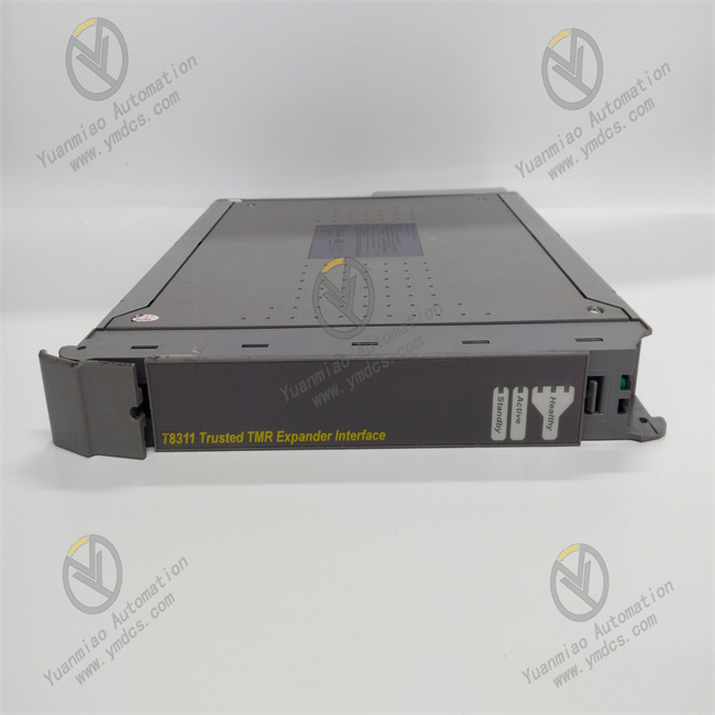
Description
The T8311 module is mainly used to achieve a safe and reliable connection between the ICS TRIPLEX controller chassis and the CS300 chassis. It supports up to 16 TMR (Triple Modular Redundancy) channels and can be connected to various field devices such as servo motors, drivers, and sensors.
Features Triple Modular Redundancy: Each module has 40 triple modular redundancy (TMR) input channels. Fault tolerance is achieved through the TMR architecture, and each field input is triplicated to improve the reliability of the system. Automatic Diagnosis and Self-check: It has an automatic diagnosis function and a self-check mechanism, which can quickly detect faults within the module itself and related connections. Line Monitoring: Each channel can independently select line monitoring and can detect open and short circuit faults in field wiring. Optical and Electrical Isolation: A 2500V pulse-resistant optoelectronic/current isolation barrier effectively isolates external interference and protects the safety of the module and the system. Event Sequence Reporting: It has an on-board event sequence (SOE) reporting with a resolution of 1 millisecond, which helps record and analyze the sequence of events, facilitating fault troubleshooting. Digital Filtering: It can be configured with a 50/60Hz digital filter to eliminate field-induced noise and improve the signal quality. Hot Swap: It supports online hot swapping of the module. Configuration can be carried out through the Companion (adjacent) slot or the SmartSlot (a spare slot for multiple modules), allowing the module to be replaced without affecting the operation of the system, thus enhancing the availability and maintainability of the system.
Working Principle The signals from field input devices are connected to the 40 input channels of the T8311 module. Each channel uses a sigma-delta input circuit to measure the input voltage. The measured field voltage value is compared with the user-configurable threshold voltage to determine the reported status of the field input. When the line monitoring function is enabled, the module can detect open and short circuits in the field cables. The triple voltage measurement mechanism within the module, combined with on-board diagnostic tests, enables efficient fault detection and fault tolerance functions. Technical Specifications Data Transmission Rate: Up to 100Mbps, meeting the requirements for fast data transmission. Operating Voltage: It supports a voltage range of 24VDC, with a rated current of 2A, and can adapt to various working environments. Application Fields It is widely used in fields such as industrial automation and process control. It can serve as the main processing component of the system, receive data from various analog and digital input/output (I/O) modules, and communicate through the trusted communication bus between TMR modules, providing overall control and monitoring functions for the system.
Common Faults and Solutions: 1. Communication Fault Fault Phenomenon: The module cannot communicate normally with other devices in the system, resulting in data transmission interruptions or errors. Possible Reasons: Poor connection of the communication line, incorrect communication protocol settings, or damage to the communication interface of the module. Solutions: Check the connection of the communication line to ensure that the plug and socket are secure and the line is intact; confirm whether the communication protocol settings match those of other devices in the system and re-set them if necessary; if the communication interface is suspected to be damaged, send the module to a professional maintenance institution for inspection and repair. 2. Power Fault Fault Phenomenon: The module cannot start normally or operates unstably, and problems such as frequent restarts and data loss may occur. Possible Reasons: Interruption of the power supply, unstable power voltage, or a fault in the internal power circuit of the module. Solutions: Check the power supply line to ensure that the power plug is properly inserted and the power switch is turned on; use a multimeter to measure the output voltage of the power supply to see if it is within the rated operating voltage range of the module. If the voltage is unstable, check whether the power adapter or power module is working properly; if a fault in the internal power circuit of the module is suspected, contact a professional for maintenance. 3. Input and Output Fault Fault Phenomenon: The input signal cannot be collected correctly, or the output signal cannot control external devices as expected, such as abnormal display of the input signal or the output relay not operating. Possible Reasons: Incorrect input and output wiring, faults in external devices, or damage to the input and output channels of the module. Solutions: Carefully check the input and output wiring to ensure that the wiring is correct and the connection with external devices is good; check whether external devices are working properly, such as whether the sensor is damaged or the actuator has a fault; if external devices and wiring problems are excluded, try to replace the input and output channels of the module, or send the module to a professional maintenance institution for inspection and repair.
4. Overheating Fault Fault Phenomenon: The module overheats during operation, and the overheating protection mechanism may be triggered, causing the module to stop working. Possible Reasons: Poor heat dissipation, long-term high-load operation of the module, or abnormal increase in power consumption due to internal component failures. Solutions: Check the installation position of the module to ensure that there is enough space around for heat dissipation and avoid being blocked by other devices; check the operation of the system to see if there is a long-term high-load operation state. If so, consider optimizing the system configuration or adding heat dissipation measures; if an internal component failure is suspected, have it inspected by a professional. 5. Abnormal Indicator Lights Fault Phenomenon: The indicator lights on the module do not light up, stay on constantly, or flash abnormally, and cannot correctly reflect the working status of the module. Possible Reasons: Damage to the indicator lights, faults in the internal control circuit of the module, or incorrect indicator light status caused by software faults. Solutions: If the indicator lights are damaged, try to replace them; for faults in the internal control circuit of the module, have it inspected and repaired by a professional; if it is a software fault, try to reset the module or re-download the configuration software to see if it can return to normal.