Description
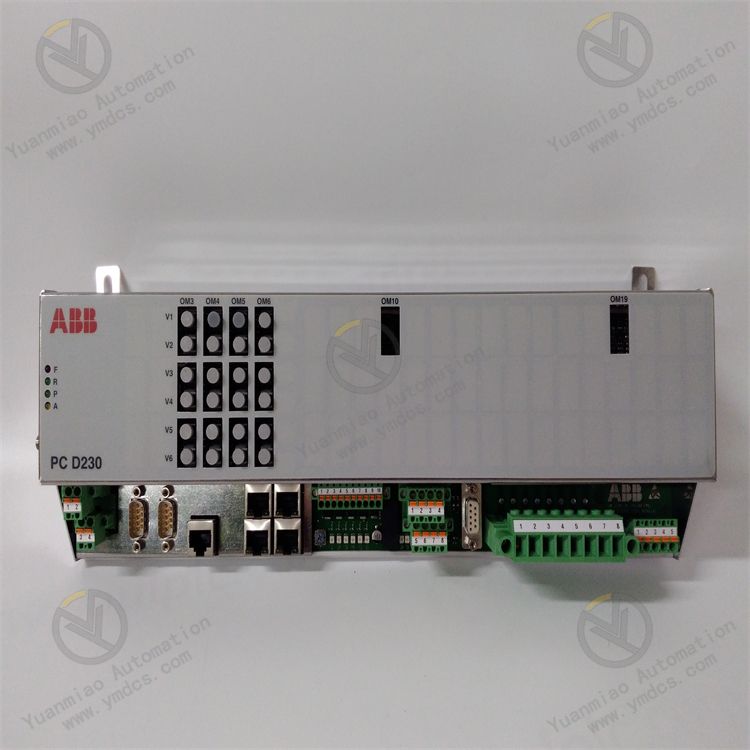
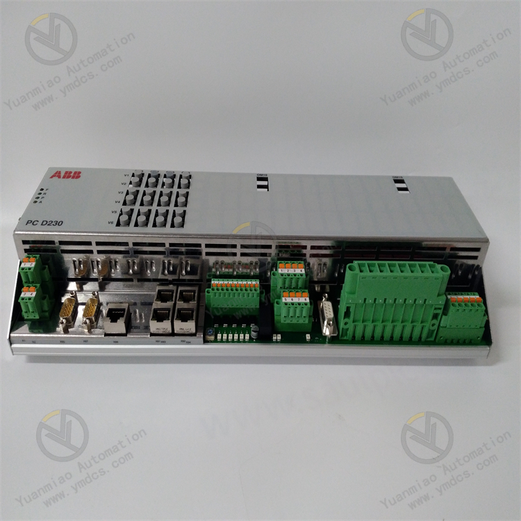
ABB PCD230A 3BHE022291R0101
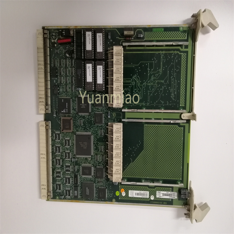
The ABB PCD230A 3BHE022291R0101 is a controller module of the AC 800M series, primarily used in Distributed Control Systems (DCS) or Programmable Logic Controllers (PLC) to achieve real-time control, data processing, and communication functions in industrial automation. Its core role is to receive sensor signals, execute control logic, and send commands to actuators through built-in processors and algorithms, while supporting communication and interaction with other devices or systems.
Functional Features
- Strong Processing Capability: Equipped with a high-performance processor and memory, it can handle complex control algorithms and tasks, providing high-speed response and real-time performance to meet the needs of complex industrial automation tasks.
- Rich Interfaces: Features multiple digital input/output modules and analog input/output modules. Digital input modules offer different channel counts, voltage levels, and current types, while analog input/output modules support various signal types and precisions, enabling connection to various sensors, actuators, and other devices for signal acquisition, control, and transmission.
- Excellent Communication Functions: Supports multiple communication protocols, enabling seamless integration with various industrial automation systems. It can be connected to networks as a master or slave station to achieve real-time data interaction between devices.
- High Reliability: Supports dual-power redundancy input with a wide-range DC 9–36V power input, featuring voltage isolation and reverse connection protection to ensure stable operation during power fluctuations or failures. Additionally, its industrial-grade design adapts to harsh environments, and it has fault diagnosis and self-detection functions to monitor module status in real time.
- Good Flexibility: Can be combined with other ABB modules to build customized control systems and supports ABB’s programming software for convenient logic development and system configuration.
Technical Parameters
- Digital Input Modules:
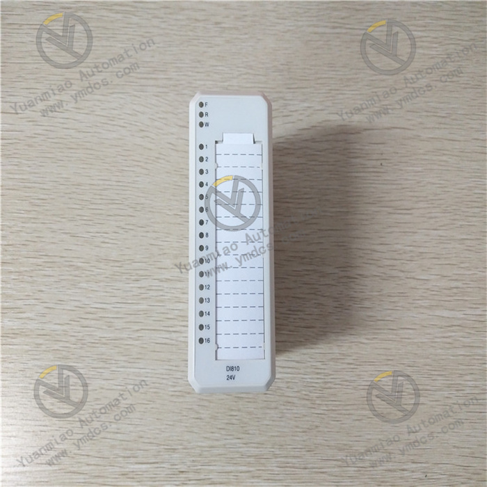
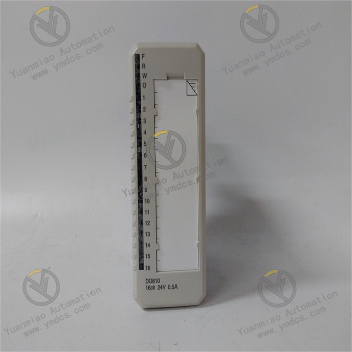
- DI810: 16 channels, 2 groups of 8 channels, 24V DC, sinking current.
- DI811: 16 channels, 2 groups of 8 channels, 48V DC, sinking current.
- DI814: 16 channels, 2 groups of 8 channels, 24V DC, sourcing current.
- DI818: 32 channels, 2 groups of 16 channels, 24V DC, sinking current.
- DI820: 8 channels, independent return, 110V DC, 120V AC.
- DI821: 8 channels, independent return, 220V DC, 230V AC.
- DI828: 16 channels, independent return, 110V DC, 120V AC/DC.
- DI890: 8 channels, independent return, 24V DC, sinking current.
- Digital Output Modules:
- DO820: 8 channels, independent return, 5–250V, max 3A AC/DC, relay (normally open).
- DO821: 8 channels, independent return, 5–250V, max 3A AC/DC, relay (normally closed).
- DO828: 16 channels, independent return, 5–250V AC/5–125V DC, max 2A AC/DC, relay (normally closed).
- Analog Input Modules:
- AI830A: 8 channels, 1 group of 8 channels, PT100, NI100, NI120, CU10, 0–400Ω resistance, 14-bit, 3-wire.
- AI843: 8 channels + reference terminal, 1 group of 8 channels, thermocouple types B, C, E, J, K, L, N, R, S, T, U, -30…75mV, 16-bit, extended diagnosis.
- AI895: 8 channels, 1 group of 8 channels, single-ended common ground, 4–20mA, 12-bit, HART interface, transmitter power supply.
- Analog Output Modules:
- AO815: 8 channels, 1 group of 8 channels, 4–20mA, 12-bit, load: max 750Ω (short-circuit protection), HART interface.
- AO820: 4 channels, independent return, isolated bipolar, ±0(2)–10V, ±0(4)–20mA, 12-bit + sign, load: max 550Ω (current)/≥2kΩ (voltage), short-circuit protection.
- AO845A: 8 channels, 1 group of 8 channels, 4–20mA, 12-bit, load: max 750Ω (short-circuit protection), extended diagnosis, HART interface.
Additional Features:
- Allows approximately 250 images and 1,024 displays per application.
- Five programmable keys enable customized functions and layouts.
- High-speed PLC with 1MB logic memory and a typical application scan time of 15 seconds per 1k.
- Provides up to 38 digital and analog I/Os, expandable to 166, including digital and analog I/Os, temperature measurement, and load battery input.
- A built-in 120GB database supports data processing and complex recipe programs.
Features of the AC 800PEC System Hardware:
- Modular and energy-efficient design, operable without forced cooling.
- I/O modules are mounted on standard DIN rails for easy installation in distributed processes.
- The number of directly connectable I/O systems is limited by the processor’s maximum available fiber optic links (36 bidirectional links). Single, multiple, or redundant bidirectional links can be used between modules according to performance requirements.
- The controller components include highly reliable low-power circuits, with flexible hardware configuration depending on process requirements and communication with upper-level controls.
Operation Guide
Installation:
- Select a stable, accessible location with sufficient space for heat dissipation. Fix the module using appropriate mounting brackets or screws.
- Connect power, signal, and control lines according to the wiring diagram, ensuring secure connections. Configure communication interfaces and set communication parameters as per system requirements.
Commissioning:
- Check the power voltage before switching on. After powering up, observe the indicator lights and display to confirm normal power supply.
- Test each function according to technical documents and perform communication tests with other devices via the communication interface.
- Integrate the module into the entire system for joint debugging and observe its operational status.
Daily Operation:
- Use configuration software or a host computer monitoring system to set parameters, monitor status, and execute control operations for the module.
- Real-time viewing of collected data and device operating status information is available. Adjust control parameters and execute control commands as needed.
Fault Troubleshooting
Power Supply Faults:
- Check if the power input is normal, including whether the voltage is within the specified range and if the power line is well-connected.
- If the power indicator light is off or abnormal, the power module may be faulty and needs replacement.
Communication Faults:
- Confirm that the communication cable connections are normal, with no damage, breaks, or short circuits.
- Check if the communication parameter settings (baud rate, data bits, stop bits, parity, etc.) match those of other devices. Replace the module or repair the interface if damaged.
Input/Output Faults:
- Check if devices connected to the module (sensors, actuators, etc.) are working properly.
- Observe the status indicator lights of the input/output channels to determine if there are channel faults. If a channel fails, try replacing the channel or checking the related wiring and devices.
System Faults:
- View the module’s fault alarm information and locate the cause based on the alarm code or prompt.
- If the module freezes or restarts abnormally, it may be a software or hardware fault. Try restarting the module or updating the software version. If unresolved, contact professional maintenance personnel.


