Description
1. Product Overview
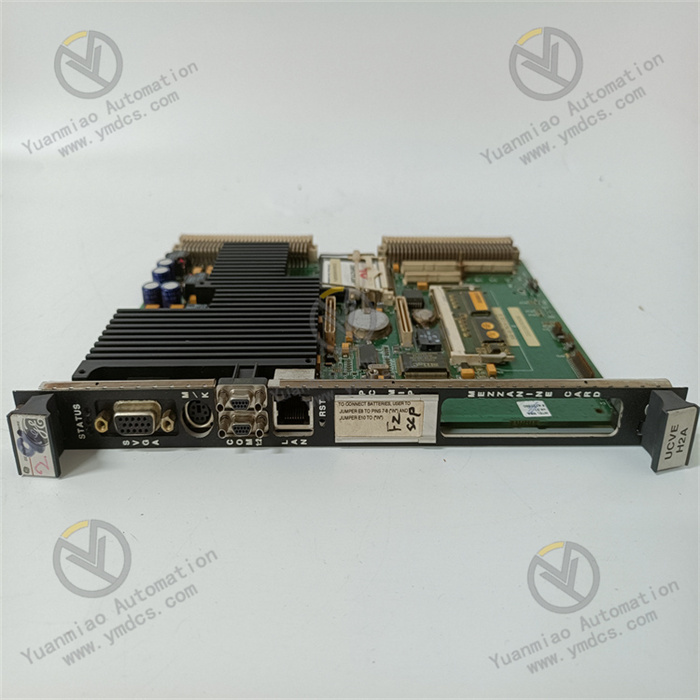
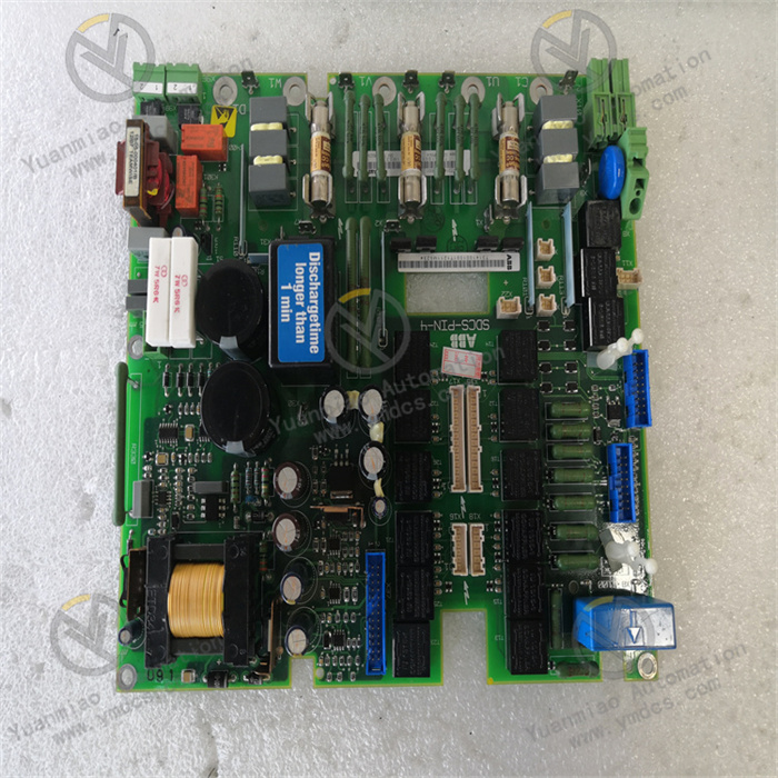
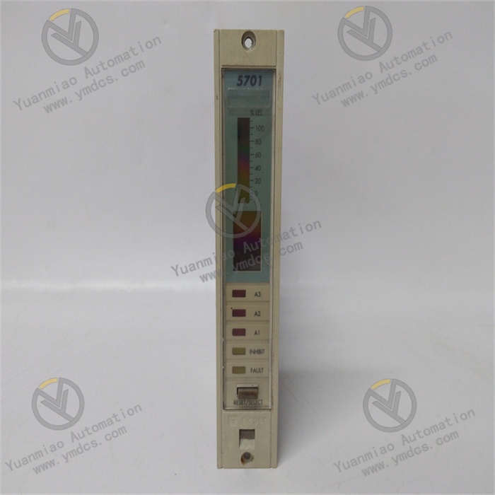
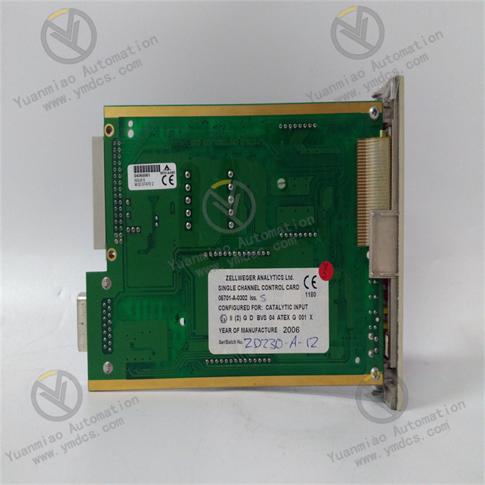
Honeywell 05701‑A‑0302 is a dedicated safety‑related I/O / communication interface module within Honeywell International Inc.’s safety automation and process control product line. It belongs to the Honeywell 05701 series safety hardware and is widely deployed with Honeywell Safety Manager, FSC (Fail‑Safe Controller), HC900 and other safety PLC/SIS systems, serving as a core component of functional‑safety‑rated control systems.
Designed for safety‑instrumented system (SIS), emergency shutdown system (ESD), burner management system (BMS), fire & gas (F&G) and critical interlock protection applications across petrochemical, nuclear‑power, oil‑gas pipeline, water‑treatment, metallurgical and power‑generation industries, this module performs acquisition, isolation, signal conditioning, communication interfacing and backplane expansion for safety‑related signals. It acts as the critical linking hardware between field loops and the main CPU of safety‑control systems.
It has passed full‑industrial and functional‑safety validation including full‑load burn‑in, thermal cycling, vibration‑shock, dielectric‑withstand and electromagnetic‑interference testing together with safety‑failure‑mode evaluation. Supporting 7×24‑hour continuous full‑load operation, it withstands harsh cabinet conditions such as elevated enclosed‑space temperature, dust‑humidity cycles, strong electromagnetic interference and mains‑voltage fluctuations. Given the large global installed base of Honeywell safety systems in high‑risk industrial plants, 05701‑series modules constitute key hardware for spare‑part replacement, on‑site maintenance and SIS/ESD modernization projects as well as strategic‑spare‑part inventory.
2. Functional Features
2.1 Functional‑Safety Certification for SIL 3 Safety Integrity
Developed and certified per IEC 61508, Honeywell 05701‑A‑0302 incorporates comprehensive hardware‑failure detection, fail‑safe output behaviour, self‑diagnostics and channel‑level redundancy. It meets SIL 3 safety‑integrity‑level requirements. Built‑in safety‑failure‑detection circuitry monitors for channel short‑circuits, open‑circuits, over‑voltage and under‑voltage as well as component malfunctions. Upon fault detection the module transitions to a predefined fail‑safe state, ensuring no dangerous failures occur under single‑point‑fault conditions and delivering robust hardware for SIS/ESD deployments in high‑hazard petrochemical and oil‑gas facilities.
2.2 Centralized Conditioning of Multiple Safety‑Related Signals
Equipped with standardized industrial terminal blocks, the module consolidates field safety‑related inputs including dry‑contact signals, proximity‑switch feedback, solenoid‑valve status, pressure‑switch and temperature‑switch contacts as well as interlock‑trip contacts. It centralizes and categorizes dispersed field safety measurement points. Following Honeywell‑original point‑assignment rules, the hardware provides clear signal partitioning with strict separation between high‑voltage and low‑voltage circuits and unambiguous terminal labelling. This eliminates problems associated with messy field‑wiring, mis‑assigned measurement points and cross‑loop interference, streamlining commissioning, loop verification and troubleshooting for standardized SIS/ESD construction and maintenance workflows.
2.3 Electrical Isolation and Enhanced Noise Immunity
Optocoupler‑based / magnetic isolation circuits together with signal‑filtering and level‑translation stages provide galvanic separation between field‑side circuits and the safety‑system backplane / CPU domain. Ground‑loop currents, common‑mode interference and surge voltages are blocked from propagating into the safety controller. Integrated over‑current protection, surge‑suppression components, varistors and ESD‑protection devices mitigate transient‑voltage surges, electromagnetic‑radiation noise and variable‑frequency‑drive harmonics. The design prevents high‑voltage cross‑coupling and power‑supply anomalies from damaging safety‑system or field‑side equipment and avoids fault‑propagation across channels, improving overall loop‑tolerance and anti‑interference performance.
2.4 Native Honeywell‑System Compatibility for Plug‑and‑Play Operation
Mechanically and electrically matched to Safety‑Manager / FSC backplane architectures, the module features compatible point‑mapping, signalling protocols, mechanical dimensions and connector pin‑outs. No additional signal‑conditioning hardware or complex calibration is required, supporting direct drop‑in replacement for both new‑build and legacy Honeywell safety‑system installations. It interfaces seamlessly with host CPUs, engineering workstations and SCADA/DCS platforms to enable real‑time safety‑signal uploads, safety‑logic execution, interlock‑coordination and status monitoring, covering new‑unit commissioning, safety‑system retrofits and loop‑reconfiguration scenarios.
2.5 Gold‑Plated Industrial Terminals for Stable Long‑Term Contact
Industrial‑grade gold‑plated anti‑corrosion terminal blocks resist oxidation, corrosion and loosening under repeated mating cycles. Maintaining stable contact resistance under cabinet vibration, high humidity, dust and oil‑contamination, they minimise risks of signal drop‑out and false safety‑state evaluation caused by poor terminal connections. Stable long‑term performance reduces unplanned‑shutdown hazards due to interlock mis‑operation and extends service life of safety‑signal loops.
2.6 On‑Board Self‑Diagnostics and Status‑Indication for Targeted Fault Localisation
Multi‑layer self‑diagnostics cover communication interfaces, individual signal channels, power‑supply rails and isolation circuitry. Front‑panel LEDs indicate power‑supply health, run‑status, channel‑condition, fault‑flags and fail‑safe mode. Using Honeywell engineering software (Safety Manager Station / Control Builder), maintenance personnel can remotely read diagnostic words, channel‑status registers and fault codes to pinpoint faulty channels without cabinet disassembly, shortening troubleshooting and repair turnaround times for safety‑system assets.
2.7 Modular Zero‑Adjustment Design for Efficient Maintenance‑Driven Replacement
Standardised hot‑swap‑compatible plug‑in mechanics ensure accurate rack‑alignment and secure latching conforming to Honeywell cabinet‑rack layout standards. Well‑defined terminal‑assignments and signal‑loop definitions allow non‑intrusive drop‑in replacement of faulty modules without safety‑logic re‑configuration, extensive rewiring or full‑plant shutdown. This reduces maintenance overhead, repair complexity and production‑loss exposure during SIS/ESD corrective‑maintenance and hardware‑upgrade activities.
3. Technical Specifications
3.1 Core Compatibility Parameters
| Item | Specification |
|---|---|
| Full Part Number | 05701‑A‑0302 |
| Brand | Honeywell (Honeywell International Inc.) |
| Product Family | 05701 Series / Safety Manager / FSC Safety‑System Modules |
| Module Type | Safety‑related I/O / Interface Module |
| Safety Rating | IEC 61508 SIL 3, TÜV‑Rheinland safety certification |
| Associated Hardware | Honeywell safety‑system rack backplane, safety CPU, power‑supply modules, communication modules |
| Core Functions | Safety‑signal input/output, galvanic isolation, circuit protection, channel self‑diagnostics, fail‑safe actuation, backplane communication |
| Typical Applications | Petrochemical‑plant SIS/ESD interlocks, oil‑gas transmission pipelines, nuclear‑protection systems, BMS, fire‑and‑gas systems |
3.2 Electrical Performance Parameters
| Item | Specification |
|---|---|
| Signal Types | Safety‑related digital / analogue signals, multi‑voltage‑range compatibility |
| Isolation Method | Optocoupler / magnetic galvanic isolation; full electrical separation between field‑side and backplane‑side circuits |
| Protection Features | Integrated over‑current, surge‑suppression, varistor and ESD protection against transient‑voltage events |
| Safety‑Behaviour | Channel‑level short‑circuit / open‑circuit detection; automatic transition to predefined fail‑safe state upon fault |
| Interfaces | Industrial screw‑type gold‑plated terminal blocks; dedicated backplane connector for CPU‑system interconnection |
| Electrical Robustness | 7×24‑hour continuous operation; immunity against signal drop‑out and contact‑resistance drift |
| Dielectric Strength | High‑voltage‑withstand rated for isolation against field‑side leakage‑current and high‑voltage cross‑coupling |
| Diagnostics | Channel‑level and board‑level multi‑layer self‑diagnostics; front‑panel LED alarm plus remote diagnostic‑word reporting |
3.3 Environmental and Mechanical Parameters
| Item | Specification |
|---|---|
| Operating Temperature | Industrial wide‑range cabinet‑grade temperature tolerance |
| Storage Temperature | Qualified for extreme‑condition storage and transportation |
| Operating Humidity | 5 %‑95 %RH (non‑condensing); resistant to dust‑laden high‑humidity cabinet environments |
| Environmental Resistance | Dust‑proof, moisture‑resistant, oil‑tolerant, thermal‑cycle resistant, vibration‑resistant, high‑EMI‑immunity |
| Mounting | Plug‑in installation onto Honeywell‑standard safety‑system racks |
| Mechanical Construction | Industrial flame‑retardant reinforced PCB with metal housing; anti‑vibration, anti‑loosening, ageing‑resistant, flame‑retardant and moisture‑resistant |
4. Hardware Configuration and Structural Advantages
4.1 Core Hardware Configuration
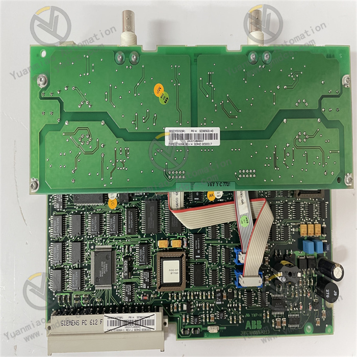
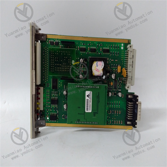
The 05701‑A‑0302 implements Honeywell‑proprietary safety‑system I/O‑module architecture incorporating multi‑channel terminal blocks, optocoupler / magnetic‑isolation stages, signal‑conditioning and filtering circuits, channel‑specific safety‑detection logic, surge‑and‑overcurrent‑protection networks, a backplane‑communication connector and dedicated power‑supply‑matching circuitry. Internal circuit partitioning strictly segregates field‑signal paths, backplane‑communication paths and auxiliary‑power‑supply domains to eliminate cross‑channel signal‑interference.
All critical components and terminal hardware pass Honeywell‑original qualification including full‑load burn‑in, thermal‑shock cycling, vibration‑fatigue, dielectric‑withstand, EMC‑immunity and safety‑failure‑mode testing. Optimised for long‑term continuous‑operation under harsh cabinet‑conditions, the hardware reliably completes acquisition, isolation, conditioning and forwarding of multi‑channel safety‑related field signals.
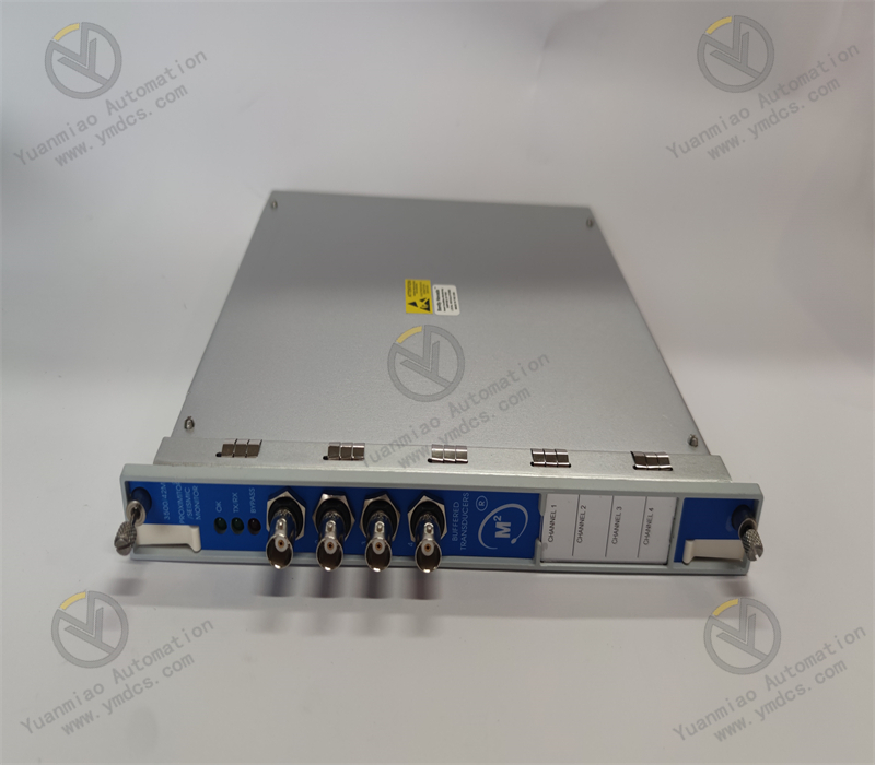
The rear‑side gold‑plated backplane connector provides robust mating with matching Honeywell‑series safety‑CPU hardware. The front‑panel hosts screw‑type field‑wiring terminal blocks and status‑LED arrays with pin‑assignments matching original‑manufacturer drawings for straightforward commissioning and maintenance. Reinforced flame‑retardant PCB construction plus mechanically secured internal assemblies mitigate risks of poor contact, terminal loosening and hardware‑degradation under cabinet vibration and thermal cycling.
4.2 Structural and Engineering‑Related Advantages
Compact standardized modular form‑factor optimises high‑density cabinet‑rack‑mounting for safety‑system enclosures. Flame‑retardant, moisture‑resistant and anti‑vibration mechanical construction plus mechanically‑locked internal assemblies deliver reliable performance under sustained vibration, thermal swings, dust and oil‑contamination. Clearly labelled partitioned terminal blocks reduce field‑wiring errors and simplify loop‑troubleshooting workflows.
Drop‑in replacement of faulty modules is supported without rack‑modification, safety‑logic‑reprogramming or full‑plant shutdown, lowering maintenance, retrofit and emergency‑repair costs for SIS/ESD assets. Uniform mechanical dimensions, terminal‑layout and commissioning‑software interfaces across Honeywell‑series I/O modules simplify spare‑part management, site‑training and corrective‑maintenance workflows, supporting long‑term stable operation of safety‑signal loops within high‑risk industrial facilities.
5. Operating Principle
The 05701‑A‑0302 safety‑related I/O‑module implements a closed‑loop safety‑signal workflow: field‑safety‑signal reception → galvanic isolation and fault‑detection → signal conditioning and backplane transmission → safety‑CPU logic execution → fail‑safe output actuation → continuous self‑diagnostics and fault‑tolerance.
During normal operation, field‑safety‑related signals (dry‑contact inputs, proximity‑switch feedback, solenoid‑valve feedback, pressure‑ / temperature‑switch contacts, interlock‑trip contacts etc.) are wired to the corresponding partitioned‑module terminals. All incoming signals pass through optocoupler / magnetic‑isolation stages to achieve galvanic separation between field‑side loops and the safety‑system backplane / CPU domain, blocking ground‑loop currents and surge‑voltage transients. Simultaneously, channel‑level safety‑detection circuitry continuously monitors each channel for short‑circuits, open‑circuits, over‑voltage and under‑voltage events.
Conditioning‑and‑filtering circuits suppress electromagnetic noise, contact‑bounce and induced‑interference pulses to produce clean‑standardised signals. Processed data is transmitted via the rear‑side backplane‑connector to the matching safety‑CPU. Under safety‑operating‑system scheduling, the CPU executes safety‑logic algorithms (interlock evaluation, SIS/ESD logic, protection‑trip‑condition‑assessment) on millisecond‑cycle intervals. Computed‑result commands are returned over the backplane to output‑modules to drive field‑safety‑actuators such as emergency‑shutdown valves, ESD solenoids and shutdown‑relays.
In parallel, the module uploads channel‑status information and diagnostic‑flags via the backplane to the safety‑CPU and host‑engineering‑station / SCADA for operator supervision. If channel short‑circuit, open‑circuit, over‑voltage or internal‑component‑failure is detected, the affected channel or the entire module transitions to the predefined fail‑safe state to prevent dangerous‑failure conditions. Continuous self‑diagnostics supervise communication integrity, loop‑health, power‑supply quality and isolation‑circuit‑performance; anomalies trigger front‑panel‑LED indication and remote diagnostic‑word alarms. Hot‑swap replacement of faulty modules is supported; after repair the system automatically synchronises channel‑status data and resumes safety‑operation.
6. Troubleshooting
6.1 Module Channel‑Fault Alarm or Fail‑Safe Activation
| Probable Cause | Diagnostic Approach | Remedial Action |
|---|---|---|
| Damaged field‑safety contact, open‑circuit or short‑circuit in field cabling | Read diagnostic‑words via engineering software; perform continuity‑measurements on field loops | Replace faulty field‑contacts / switches; repair broken or short‑circuited cables |
| Loose, oxidised or poorly‑mated field‑terminal connections | Review channel‑status trends; inspect terminal‑block crimp‑integrity on‑site | Tighten terminals; clean or replace oxidised terminals; re‑crimp cable lugs |
| Failure of module‑internal isolation‑or‑detection‑circuitry | Inject reference‑signals or perform short‑loop‑tests at module‑input terminals to evaluate channel‑response | Replace 05701‑A‑0302 module; restore channel‑configuration parameters |
| Channel‑mis‑diagnosis triggered by field‑site electromagnetic‑interference | Observe whether faults correlate with motor‑ / variable‑frequency‑drive switching events | Improve cable‑shield‑earthing; separate signal‑cable routing from power‑cable‑routing |
6.2 Total Module‑Communication Loss or Abnormal Backplane‑Data
| Probable Cause | Diagnostic Approach | Remedial Action |
|---|---|---|
| Loose, oxidised or pin‑retention‑failure at backplane‑connector | Extract module for visual inspection of gold‑plated fingers and backplane‑receptacle pins | Clean connector‑fingers and receptacle‑pins; firmly re‑seat and latch module; repair backplane in case of pin‑retention‑failure |
| Fault in companion safety‑CPU module | Inspect CPU‑front‑panel‑LEDs and system‑alarm‑logs | Perform hot‑swap replacement of faulty CPU per‑site‑procedures; no modification required for this I/O‑module |
| Cabinet‑supply‑voltage deviation or faulty rack‑power‑supply | Measure backplane‑supply‑voltage against nominal‑specifications | Troubleshoot cabinet‑power‑supply‑circuits; replace defective power‑supply‑module |
6.3 Unintended Safety‑Interlock Trip or Failure‑to‑Trip on Demand
| Probable Cause | Diagnostic Approach | Remedial Action |
|---|---|---|
| Erroneous safety‑logic‑configuration or incorrect logic‑download | Monitor online safety‑logic‑blocks and input‑variable‑states | Restore validated prior‑revision‑logic; redeploy configuration following formal MOC (Management‑of‑Change) procedures |
| Poor‑contact‑resistance at field‑safety‑contacts leading to false‑interlock evaluation | Measure interlock‑loop resistance and contact‑closing‑quality | Clean or replace safety‑contacts; rectify excessive‑loop‑resistance |
| Faulty output‑module‑drive‑circuitry or sticking‑solenoid‑actuator | Check output‑channel‑status indicators; inspect solenoid‑ / actuator‑hardware locally | Repair output‑module‑hardware; replace defective solenoid‑valves or field‑actuators |