Description
Functional Features Multiple Input Types: It supports various types of sensor inputs, including thermocouples, resistance temperature detectors (RTDs), strain gauges, and voltage signals, etc. This enables it to adapt to different measurement requirements and can be widely applied to the measurement of physical quantities such as temperature, pressure, and force. High-precision Measurement: It has the ability of high-precision signal conditioning and can provide accurate measurement results. It can perform processing such as amplification, filtering, and linearization on the input signals, reducing measurement errors and improving measurement accuracy. Isolation Function: It has the characteristic of electrical isolation, which can isolate the sensor signals from other parts of the data acquisition system, effectively preventing electrical interference and ground loop problems, and improving the stability and reliability of the system. Configurability: Users can flexibly configure the module through software, such as setting the measurement range, filtering parameters, input types, etc., to meet different application requirements. This configurability gives the module high versatility and flexibility.
Technical Parameters Number of Input Channels: It usually has multiple input channels, such as 8 channels or 16 channels, which can condition and collect multiple signals simultaneously, improving the collection efficiency of the system. Measurement Range: For different input types, it has different measurement ranges. For example, for thermocouple inputs, the measurable temperature range is usually from -200°C to +1800°C; for voltage inputs, the measurement range can be ±10V, etc. Accuracy: It has high accuracy. For example, in temperature measurement, the accuracy can reach ±0.1°C or higher. Sampling Rate: It supports a certain sampling rate, which can be set according to actual application requirements. Generally, it can reach several thousand Hz or even higher to meet the requirements for collecting rapidly changing signals.
Application Fields Industrial Automation: In the industrial production process, it is used to monitor and control various physical quantities, such as temperature, pressure, flow rate, etc., to ensure the stability of the production process and the consistency of product quality. For example, in chemical production, it can be used to monitor the temperature and pressure of the reaction kettle to achieve automated control of the production process. Environmental Monitoring: It can be used for the monitoring of environmental parameters, such as temperature, humidity, air pressure, etc. In places such as weather stations and environmental monitoring stations, by collecting sensor signals, it can achieve real-time monitoring and analysis of environmental data. Experimental Research: In scientific research experiments, it is often used for data collection and signal conditioning. For example, in materials mechanics experiments, by collecting strain gauge signals, it can measure the deformation of materials under different loads; in electronic circuit experiments, it is used to collect signals such as voltage and current to analyze the performance of the circuit.
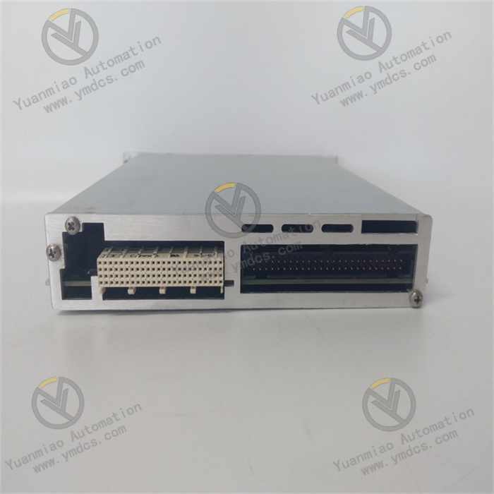
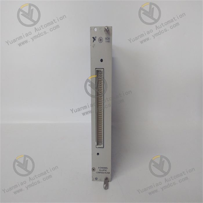
Operation Guide: I. Hardware Installation Steps 1. Preparation Work Required Tools: Anti-static wrist strap, screwdriver, SCXI chassis (such as SCXI-1000 or SCXI-1001), power module (such as SCXI-1121), data cable (such as PXI or PCI bus cable). Safety Measures: Wear an anti-static wrist strap to avoid damaging the module due to static electricity; ensure that the power supply of the chassis is turned off. 2. Physical Installation Insert the Module: Insert the SCXI-1141 module vertically into the slot of the SCXI chassis, ensure that the connector at the bottom of the module is fully aligned with the chassis slot, and then gently press the module until it is fixed in place. Fix the Module: Use a screwdriver to tighten the screws on both sides of the module to ensure that the module is firmly installed in the chassis to prevent it from loosening. Connect the Sensor: According to the sensor type (thermocouple, RTD, strain gauge, etc.), connect the sensor cable to the input end of the module. Pay attention to the matching of polarity and signal type. 3. System Connection Connect the Chassis Power Supply: Insert the power module into the SCXI chassis and connect the external power supply (usually 24V DC). Connect the Data Acquisition Device: Use a PXI or PCI bus cable to connect the SCXI chassis to the data acquisition card of the computer (such as NI PXI-6259). Grounding: Ensure that the SCXI chassis and all devices are correctly grounded to reduce interference.
II. Software Configuration Steps 1. Install the Driver Download the Driver: Visit the official website of NI to download the latest NI-DAQmx driver (suitable for Windows systems). Install the Driver: Run the installation program and complete the driver installation according to the prompts. After the installation is complete, restart the computer. 2. Configure the Module Open NI MAX: Find and open "NI MAX" (NI Measurement & Automation Explorer) in the Windows Start menu. Detect the Device: In the left panel of NI MAX, expand "Devices and Interfaces", right-click on "NI-DAQmx Devices", and select "Find New Devices". The system will automatically detect and identify the SCXI-1141 module. Configure the Channel: Double-click the detected SCXI-1141 module to enter the configuration interface. Select the "Channel" tab and click "New" to create a new measurement channel. Select the corresponding channel type according to the sensor type (such as thermocouple, RTD), and set parameters such as the measurement range and unit. Configure the physical connection information (such as channel number, sensor location). 3. Set the Electrical Isolation In NI MAX, right-click on the SCXI-1141 module and select "Properties". In the "Module Configuration" tab, enable the "Electrical Isolation" function and set the isolation voltage level (usually 1500Vrms). 4. Test the Configuration In NI MAX, select the configured channel and click the "Test Panel". Input an analog signal (such as a temperature value) and observe whether the collected data is consistent with the input value. If the test fails, check whether the hardware connection and configuration parameters are correct.

III. Common Problems and Solutions
The module cannot be detected:
Check whether the hardware connection is firm and re-plug the module.
Confirm that the power supply of the SCXI chassis is turned on and working properly.
Manually refresh the device list in NI MAX.
Inaccurate data collection:
Check whether the sensor type and range settings are correct.
Check whether the cable connection is good and whether there are interference sources.
Perform zero and full-scale calibration (which can be operated in NI MAX).
The isolation function fails:
Ensure that the isolation voltage setting of the module meets the requirements.
Check whether the grounding is correct to avoid forming a ground loop.
V. Precautions
Anti-static: Be sure to wear an anti-static wrist strap before operating the module to avoid damaging sensitive components due to static electricity.
Power Requirements: Ensure that the power supply of the SCXI chassis is stable and the voltage fluctuation does not exceed the specified range.
Cable Management: Keep the signal cables separated from the power cables to reduce electromagnetic interference.
Regular Maintenance: Regularly clean the module and the chassis and check whether the connections are loose.