Description
Working Principle: Scanning Cycle Working Mode: The CPU performs a periodic cyclic scan according to the program prepared by the user according to the control requirements and stored in the user memory, based on the instruction step number (or address number). If there is no jump instruction, it executes the user program step by step starting from the first instruction until the program ends, and then returns to the first instruction to start a new round of scanning. A scanning cycle includes three stages: input sampling, program execution, and output refreshing. Input Sampling Stage: First, it reads in the on-off status or input data of all input terminals temporarily stored in the input latch in a scanning manner, and writes them into the corresponding input status registers to complete the input refreshing. After that, the input port is closed and enters the program execution stage. Program Execution Stage: It scans and executes each instruction in the order of the user program instructions. After corresponding operations and processing, the results are written into the output status register, and the content in the output status register will change as the program is executed. Output Refreshing Stage: When all instructions are executed, the on-off status of the output status register is sent to the output latch during the output refreshing stage, and is output through certain means (such as relays, transistors, or thyristors) to drive the corresponding output devices to work. Differences from Traditional Relay Control and Handling: Different Operation Modes: Traditional relay control adopts a hard logic parallel operation mode, that is, when the relay coil is powered on or off, all its contacts will act simultaneously immediately; while in the CC - TCF901 program module, if an output coil or logic coil is turned on or off, all the contacts of this coil will not act immediately, and they will act only when the contact is scanned. Application of Scanning Technology: Considering that the action time of various contacts of the relay control device is generally more than 100ms, and the time for the PLC to scan the user program is generally less than 100ms, to eliminate the differences caused by the different operation modes of the two, the CC - TCF901 adopts scanning technology, enabling it to simulate the effect of relay control to a certain extent, while also possessing the flexibility and programmability of computer control.
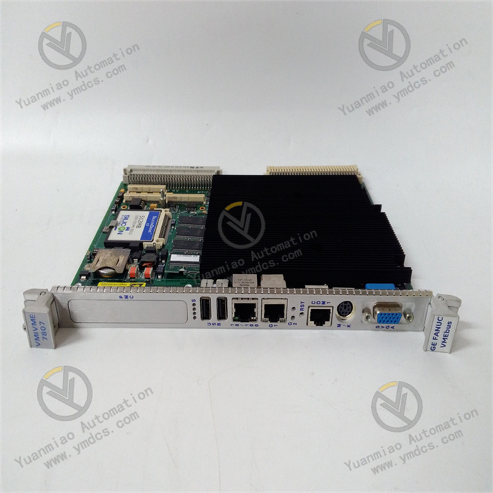
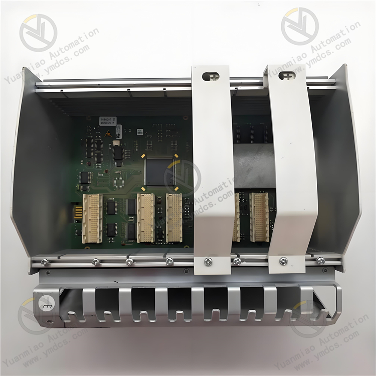
Features Strong Communication Processing Ability: As a communication processor module, it can handle multiple communication protocols, act as a bridge between different protocols or networks, achieve seamless data exchange and integration within the control system, and enhance the connectivity and interoperability between different components. High Reliability: It has high reliability, stability, and anti-interference ability. Adopting industrial-grade design and manufacturing processes, it can work stably in harsh industrial environments such as petrochemical and power industries. Rich Digital Interfaces: As an input/output terminal component, it supports multiple input and output interfaces and protocols, can be connected and communicate with various types of devices and controllers, receive input signals from the field and convert them into a format understandable by the controller, and at the same time convert the output signals of the controller into a format understandable by the field devices. Technical Parameters Input and Output Type: Digital quantity. Number of Input and Output Points: Usually, there are 4 input points and 4 output points. Communication Protocol: Supports protocols such as Modbus TCP/IP. Power Supply: Generally 24V DC. Communication Speed: 10/100Mbps. Operating Temperature Range: -40°C to 85°C. Size: 100mm x 80mm x 25mm.

Common Faults and Solutions
Communication Fault
Fault Phenomenon: The module cannot establish communication with other devices, or data loss, errors, etc. occur during the communication process.
Solution: Check whether the communication cable is firmly connected, and whether there is any damage or disconnection; confirm whether the communication interface is damaged; check whether the communication parameter settings of the module and other devices, such as baud rate, data bits, stop bits, parity bits, etc., are consistent; check whether network devices (such as switches, routers, etc.) are working properly and whether the network configuration is correct.
Power Supply Fault
Fault Phenomenon: The indicator light of the module does not light up, or the module cannot work properly.
Solution: Check whether the power supply is normal and measure whether the input power supply voltage is within the specified range; check whether the power connection cable is well connected, and whether there is any looseness or disconnection; if the power supply voltage is abnormal, check whether the power supply device is faulty.
Input and Output Fault
Fault Phenomenon: The input signal cannot be correctly collected, or the output signal cannot control the field device.
Solution: Check whether the input and output connection lines are correct and firm, and whether there is any short circuit or open circuit; confirm whether the type and range of the input and output signals are consistent with the module configuration; check whether the field device is working properly and whether there is any fault; refer to the user manual of the module to check if there are relevant error codes and troubleshoot according to the prompts.