Description
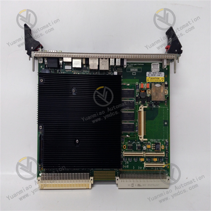
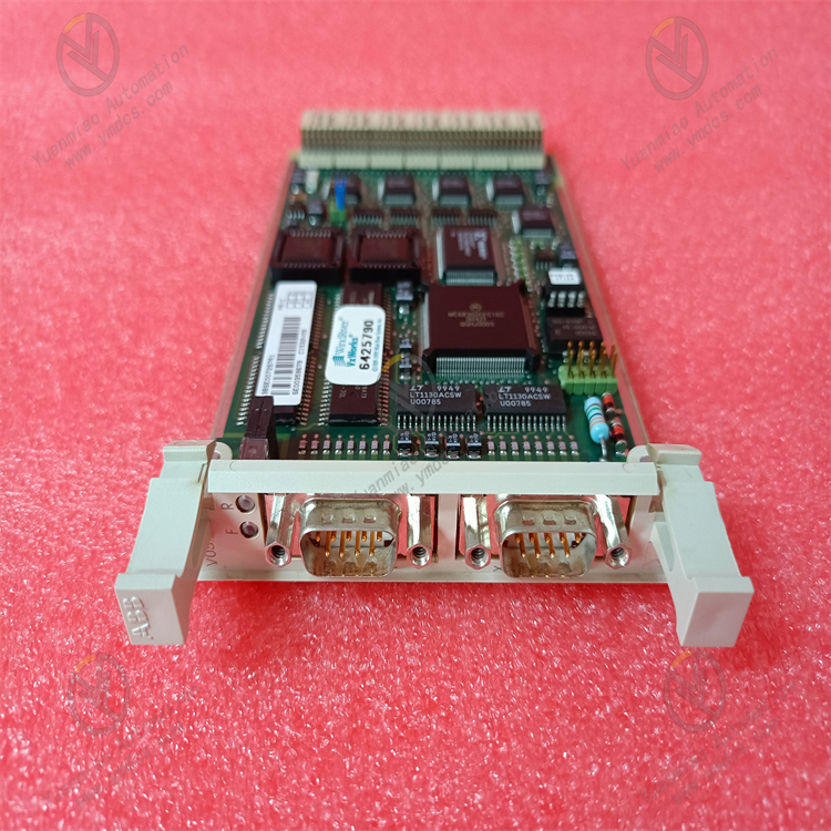
ABB CI532V02 3BSE003827R1
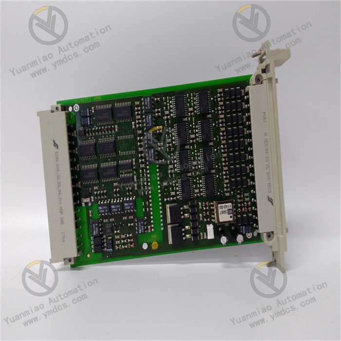
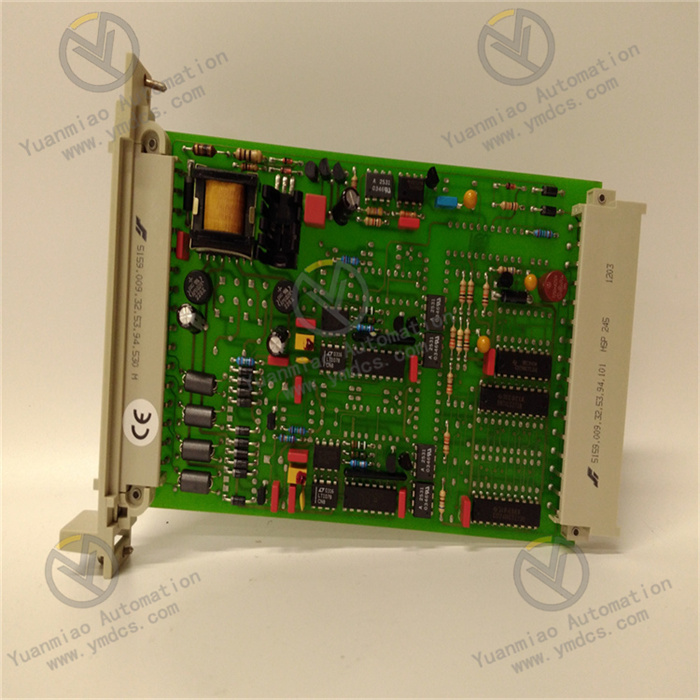
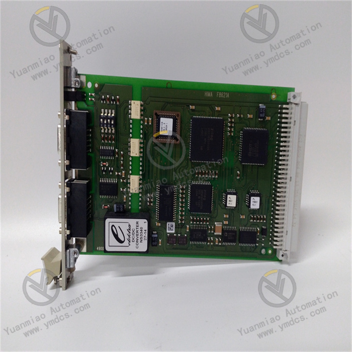
ABB CI532V02 3BSE003827R1 is a communication module specifically designed for industrial automation systems.
Features and Applications
Rich Communication Protocol Support: Supports multiple communication protocols such as Modbus TCP, Ethernet/IP, and Profinet IO, enabling seamless integration into various industrial control systems and devices to meet communication needs in different industrial scenarios.
Efficient Data Transmission: Features high-speed data transmission capabilities to ensure rapid exchange of real-time data, which is particularly critical for automation control systems requiring fast responses.
High Reliability: Designed with a focus on industrial-grade reliability and stability, it can operate stably for long periods in harsh industrial environments, reducing production interruptions caused by communication failures.
Flexible Configuration: The module offers flexible configuration options and supports scalability to adapt to future upgrades or additions of communication functions. Its compact design facilitates easy installation and integration, while user-friendly maintenance interfaces allow technicians to perform fault diagnosis and daily maintenance with ease.
Technical Parameters
- Operating Voltage: Typically 24VDC.
- Communication Interface: Modbus interface with 2 channels.
- Product Model: CI532V02, Product Number: 3BSE003827R1.
- HS Code: 85389091.
Troubleshooting Steps and Solutions for Communication Faults in ABB CI532V02 3BSE003827R1 Communication Module
1. Initial Fault Information Collection
Confirm Fault Symptoms
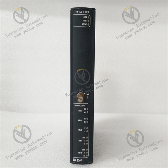
- Status of module indicator lights (e.g., power light, communication light abnormalities).
- Presence of error codes or logs (viewable via programming software).
- Whether the communication interruption is persistent or intermittent? Does it occur alongside equipment start/stop, voltage fluctuations, or other scenarios?
Check Hardware Connections
- Power Supply: Measure the module's supply voltage to ensure it is 24VDC±10% (refer to similar module specifications). Verify that the power adapter and terminal connections are secure, free from looseness, oxidation, or short circuits.
- Communication Cables:
- Use shielded twisted-pair cables and check for reversed, loose, or damaged RS485/A/B wires.
- Ensure proper termination resistor connection (e.g., add a 120Ω resistor at the end of multi-node networks; the module may have a built-in resistor enabled via a jumper cap).
- Check if the cable length exceeds the protocol's maximum transmission distance (e.g., Modbus RTU recommends <1200 meters).
- Grounding: Ensure the shield layer is grounded at a single point (connected to the control cabinet's metal shell) to avoid electromagnetic interference.
2. Module Status and Parameter Verification
Indicator Light Analysis (Refer to Similar Module Logic)
| Indicator | Normal Status | Abnormal Status and Possible Causes |
|---|---|---|
| PWR (Power) | Constant on | Off: Power failure or module damage; Flashing: Unstable voltage |
| COM (Communication) | Periodic flashing | Off: No communication signal; Constant on: Communication anomaly or parameter error |
| ERROR (Error) | Off | On/Flashing: Hardware failure, protocol mismatch, or data error |
Communication Parameter Configuration Check
- Confirm via ABB Control Builder M or programming software:
- Slave Address: Is it unique (range such as 1-247) and matched with the master station?
- Baud Rate: Such as 9600, 19200, etc., must fully match the master and slave devices.
- Data Format: Are data bits (8 bits), stop bits (1/2 bits), and parity (none/odd/even) matched?
- Protocol Type: Is Modbus RTU or another supported protocol correctly selected (CI532V02 is typically used for Modbus communication)?
Network Conflict Troubleshooting
- Are there duplicate slave addresses on the same network?
- Is there an IP address conflict (only applicable to Ethernet modules; no need to check if CI532V02 is a serial module).
3. Scenario-Based Fault Troubleshooting
Scenario 1: No Power Supply or Abnormal Power Supply
- Troubleshooting Steps:
- Use a multimeter to measure the voltage at the power terminals. If it is 0V, check the upstream power switch, fuse, or power distribution module.
- If the voltage is low (e.g., <21.6V), check the power cable gauge, terminal contact, or excessive power load.
- Solutions:
- Replace power cables or tighten terminals; upgrade power capacity if necessary.
- If the module overheats, internal short-circuit may occur, requiring module replacement.
Scenario 2: Abnormal Communication Indicator (COM Light Not Flashing or Constant On)
- Troubleshooting Steps:
- No response: Possible slave address error or communication parameter mismatch.
- Erroneous response: Possible parity error or data frame format error.
- Confirm that the master station is working normally (e.g., PLC program running, no communication port faults).
- Use a serial debugging tool (e.g., Modbus Poll/Slave) to directly connect to the module and send test commands (e.g., read holding registers) to observe the module's response:
- Solutions:
- Reconfigure the slave address and communication parameters to ensure consistency with the master station.
- Check cable polarity (whether RS485_A/B are reversed) and replace the cable for testing.
Scenario 3: Communication Interruption or Data Errors
- Troubleshooting Steps:
- Check for strong electromagnetic interference sources (e.g., frequency converters, motors) around the module, causing signal distortion.
- Test the loop resistance and insulation resistance of communication cables to confirm no short circuits, open circuits, or grounding faults.
- Test in single-node mode (only module and master station connected) to eliminate multi-device networking conflicts.
- Solutions:
- Shield communication cables or keep them away from interference sources, ensuring good grounding.
- Enable the module's line redundancy function (if supported) or replace with higher-quality cables.
- For multi-node networking, check proper termination resistor connection and whether the number of nodes exceeds the module's maximum support (e.g., CI532 typically supports ≤32 nodes).
Scenario 4: Software or Firmware Issues
- Troubleshooting Steps:
- Check the module's firmware version via programming software to see if it is the latest (refer to updates released on ABB's official website).
- Attempt to restore factory settings (backup configurations in advance) and redownload parameters.
- Solutions:
- Upgrade the firmware to the officially recommended version, noting that a power cycle is required to take effect.
- If factory restoration is ineffective, a module storage chip failure may occur, requiring return for repair or replacement.
4. Replacement Testing and System-Level Debugging
Replacement Testing
- Install the faulty module into a normally operating same-model system and observe communication:
- If normal, the original system may have power supply, grounding, or network interference issues.
- If still faulty, the module hardware may be damaged (e.g., communication chip, circuit board failure), requiring replacement.
- Replace the original module with a spare module to test if communication is restored and confirm whether the defect lies with the module itself.
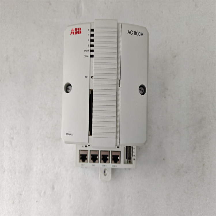
System-Level Coordination Testing
- Integrate with controllers (e.g., ABB AC 800M series) and HMIs to simulate actual working conditions for data transmission/reception testing. Check for program logic errors (e.g., too short timeout settings, register address conflicts).