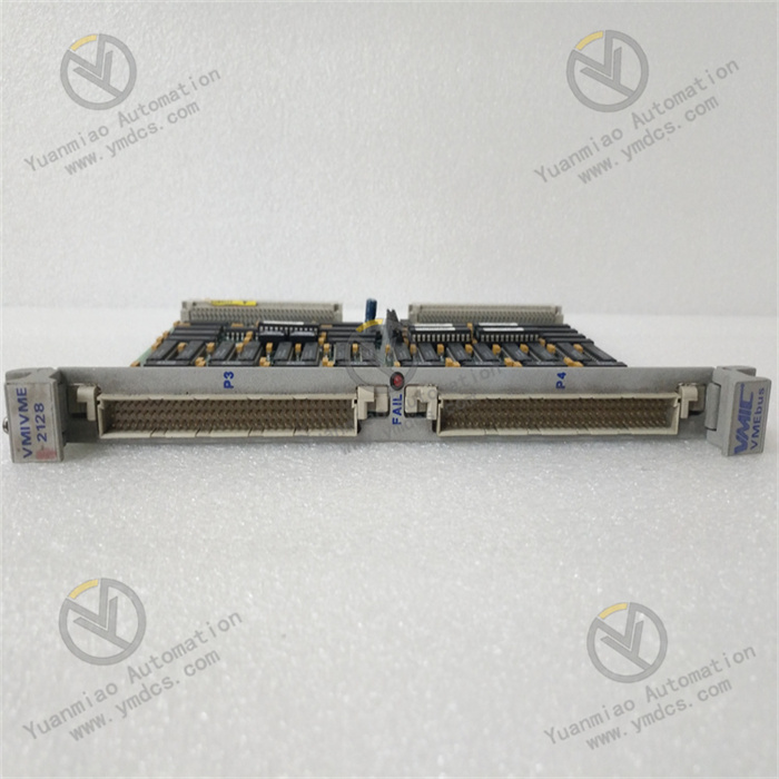
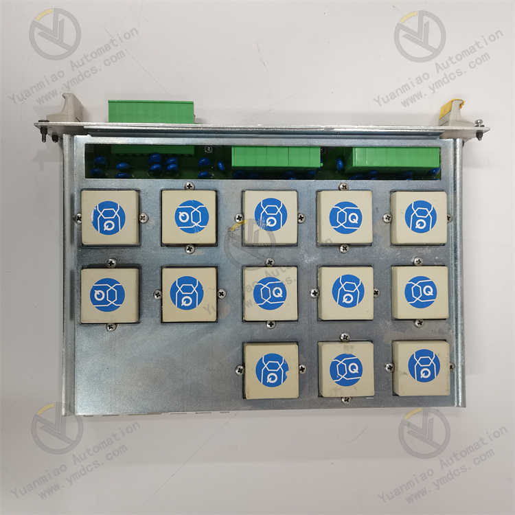
Description
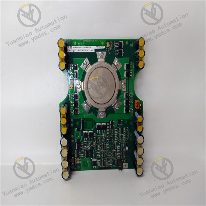
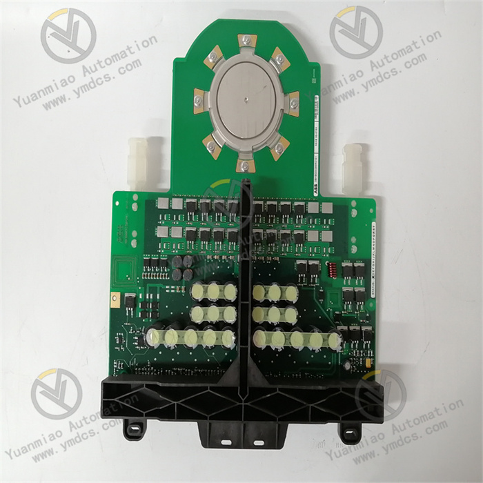
ABB 500MTM02 1MRK001967-AA 1HDF 930512 X010
The ABB 500MTM02 1MRK001967-AA is an Input/Output (I/O) module widely used in industrial automation systems. It connects field devices with control systems to enable data acquisition and transmission of control commands.
Key Features
- High-Performance Data Processing: Capable of fast and reliable handling of large-scale data exchange to ensure efficient system operation.
- Multi-Protocol Support: Compatible with multiple industrial communication protocols such as Modbus, PROFIBUS, and Ethernet/IP, facilitating integration with diverse devices and systems.
- Flexible Configuration Options: Supports multiple configuration methods to meet different application requirements, while being easy to install and maintain.
- Robust and Durable: Complies with industrial standards, ensuring long-term stable operation in harsh environments such as high temperature, humidity, and strong electromagnetic interference.
Technical Specifications
- Input Voltage: 24V DC.
- Digital Input/Output: Specific quantities vary by model and configuration.
- Analog Input/Output: Specific quantities vary by model and configuration.
- Communication Interfaces: Supports protocols including Modbus, PROFIBUS, and Ethernet/IP.
- Operating Temperature: -20°C to +70°C.
Application Areas
- Process Control: Suitable for automation control in industries such as chemical and oil & gas, enabling precise monitoring and control of various parameters in production processes.
- Manufacturing: Commonly used for automated production line control, connecting various devices on the line to achieve collaborative operation and data sharing, improving production efficiency and product quality.
- Energy Management: Plays a role in power system monitoring and control, ensuring reliable communication between devices in the power system and safeguarding its safe and stable operation.
- Building Automation: Used for data exchange in building automation systems to enable intelligent control of devices such as lighting, air conditioning, and elevators within buildings.

Operation Guide for ABB 500MTM02 Module
1. Installation and Connection
- Device Inspection: Before installation, verify that the module is free from physical damage, complete with accessories, and check whether its specifications (e.g., input voltage, communication interfaces) match the actual application requirements.
- Module Installation: Install the module in a suitable location according to ABB’s installation manual, ensuring firm installation. Avoid high-temperature, humid, or strong electromagnetic interference environments. Typically, the module should be installed in a control cabinet for easy wiring and maintenance.
- Power Connection: Correctly connect a 24V DC power supply to the module’s power input, paying attention to the positive and negative polarity. Use a multimeter to measure the input voltage and ensure it falls within the allowable range (usually ±10% of the rated voltage).
- Communication Cable Connection: Connect appropriate communication cables based on the communication requirements with other devices. For example, use RS-485 or RS-232 cables to communicate with Modbus-compatible devices, or Ethernet cables for Ethernet/IP communication. Ensure secure connections without looseness or short circuits, and configure parameters (e.g., station address, baud rate) according to the communication protocol requirements.
- I/O Signal Connection: Connect input signals (e.g., sensor signals) to the module’s digital or analog input terminals, and connect output devices (e.g., relays, contactors) to the digital or analog output terminals based on specific control tasks. Ensure that the signal type (digital/analog), voltage level, and current capacity match the module’s specifications to avoid overload damage.
2. Parameter Configuration
- Basic Parameter Setup: Use the module’s built-in configuration software or host monitoring software to set basic parameters, such as device name, communication parameters (station address, baud rate, communication protocol), and types/ranges of I/O signals. These settings must align with the requirements of the connected devices and systems to ensure proper communication and data interaction.
- Functional Parameter Configuration: Configure relevant functional parameters based on specific control needs. For example, set control algorithm parameters (e.g., PID parameters) for process control, or adjust sampling frequency and filtering parameters for data acquisition. Refer to the module’s technical manual or relevant documentation for detailed setup methods and parameter definitions.
3. Operation and Monitoring
- Module Startup: After installation and parameter configuration, power on the module and wait for initialization. The module typically has indicator lights (e.g., power indicator, communication indicator) to display its operating status. Observe these indicators to confirm normal startup. If anomalies are detected, refer to the fault diagnosis section of the module manual for troubleshooting.
- Operation Monitoring: Use host monitoring software or the module’s built-in monitoring functions to real-time monitor its status, including I/O signal values, communication status, and device operating parameters. Timely identify and address issues—for example, check sensors or connection cables if an input signal is abnormal, or verify communication cables and parameter settings if communication indicators malfunction.
- Data Recording and Analysis: Configure the module to record and store relevant data as needed for subsequent analysis. For example, log key parameter changes in production processes, equipment runtime, and fault timestamps/causes. Analyzing this data can optimize production processes, predict equipment failures, and enhance system reliability and efficiency.