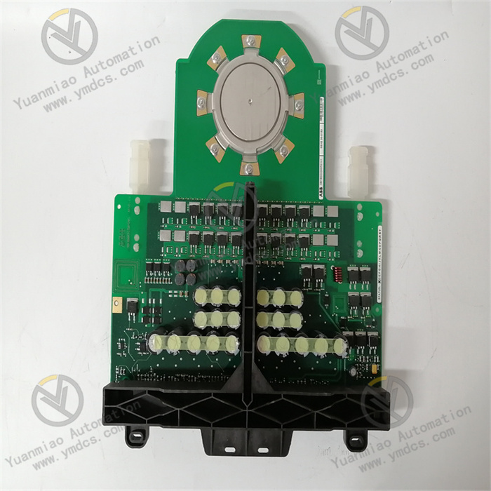
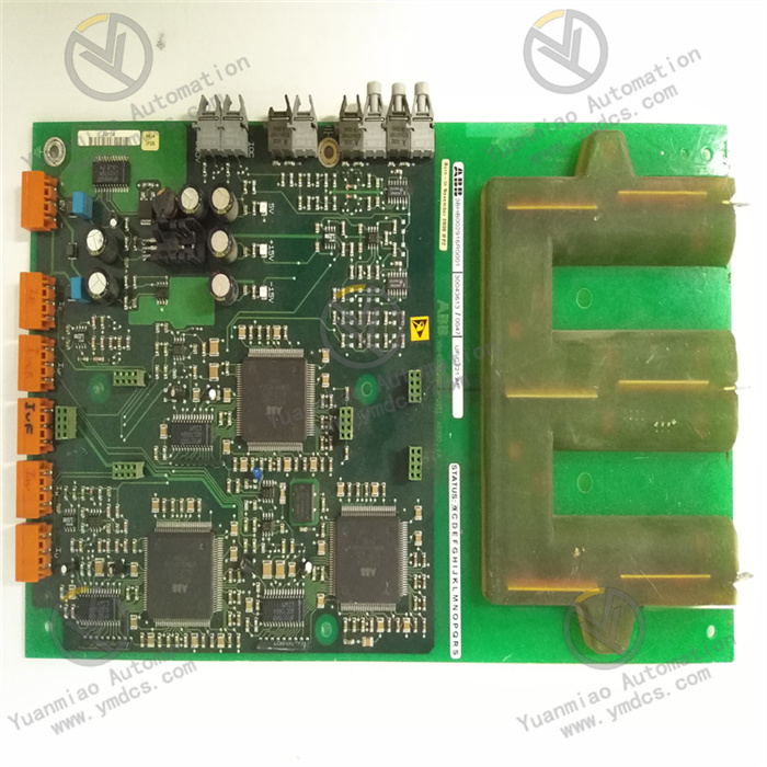
Description
ABB CI862K01 3BUA000037R1
Technical Parameters
Operating Voltage: 220V
Output Frequency: 60KHz
Communication Capability:
Output Frequency: 60KHz
Communication Capability:
- Supports direct connection to one TRIO LAN, enabling 30 blocks to be connected to a single LAN, and provides a port for handheld displays.
- The AC 800M can have up to four single LANs or four redundant LANs. TRIO supports CEX module redundancy.
I/O Points: - The maximum I/O for TRIO in AC 800M is 1000 IO points. The CI862 unit can handle I/O configuration and scanning for up to 30 TRIO blocks.
Functional Features: - High-performance control capability, supporting fast and accurate data processing and decision-making.
- Integrates functions such as data acquisition, signal processing, logical control, and communication interfaces.
- Programmable, supporting multiple programming languages and development environments.
Reliability: - Rigorously tested and verified for high reliability and stability, capable of long-term operation in harsh industrial environments.
Communication Protocols: - Supports multiple communication interfaces and protocols, enabling integration with various industrial communication networks for real-time data transmission and remote monitoring.

Functional Characteristics
1. Communication and Network Integration Capability
Multi-Protocol Compatibility
- Supports the TRIO LAN communication protocol, enabling direct connection to TRIO network devices (e.g., remote I/O, sensors, actuators) for high-speed data transmission.
- Compatible with the CEX bus redundancy architecture of ABB AC 800M control systems, supporting integration with CPU redundancy and bus redundancy modules (e.g., BC810) to enhance system reliability.
Flexible Network Topology - A single module can manage 30 TRIO blocks and connect to the AC 800M controller via TRIO LAN, supporting up to 4 independent or redundant LAN networks to adapt to distributed deployment needs in complex industrial scenarios.
- Provides a handheld display port for convenient on-site debugging and monitoring.
2. High-Performance Data Processing and Control
High-Speed I/O Handling
- Supports real-time scanning and processing of up to 1000 I/O points, meeting data acquisition and command response requirements in high-speed industrial control scenarios (e.g., real-time production line monitoring, motion control).
- Equipped with a high-performance processor, supporting fast logical operations, signal processing, and closed-loop control, suitable for real-time automation tasks (e.g., motor drive control, process parameter adjustment).
Programmability and Functional Expansion - Supports configuration and programming via ABB engineering software (e.g., Control Builder M), compatible with IEC 61131-3 standard programming languages (e.g., Ladder Diagram LD, Structured Text ST) to facilitate user-defined control logic.
- Enables functions such as data filtering, alarm triggering, and custom communication cycles through software configuration, flexibly adapting to different process requirements.
3. Reliability and Industrial-Grade Design
Redundancy and Fault Tolerance
- Supports TRIO network redundancy and module-level redundancy (requires redundant CEX bus modules), reducing single-point failure risks and ensuring continuous system operation during communication interruptions or module failures.
- Built-in diagnostic functions provide real-time feedback on operational status via LED indicators (e.g., power, communication status, fault alarms) for quick fault 定位 and resolution.
Harsh Environment Adaptability - Designed to industrial standards, with an operating temperature range of 0°C ~ 55°C, storage temperature of -40°C ~ 70°C, humidity tolerance of 5% ~ 95% (non-condensing), and IP20 protection level, resisting dust, vibration, and electromagnetic interference, suitable for harsh scenarios in power, chemical, and manufacturing industries.
4. Modular and Convenient Installation
Standardized Installation Architecture
- Uses 35mm DIN rail mounting for plug-and-play compatibility, seamlessly integrating with AC 800M controllers, S800 I/O systems, and third-party PROFIBUS/Fieldbus devices to simplify system setup.
- Supports expansion via base plates (e.g., TP series), enabling quick connection of power, communication cables, and I/O devices through physical interfaces to reduce wiring complexity.
Flexible System Expansion - In AC 800M control systems, a single controller can be configured with multiple CI862K01 modules to expand system I/O capacity and communication port count, meeting requirements for large-scale automation projects.
5. Application Scenario Adaptability
- Industrial Automation: Suitable for scenarios requiring high-speed communication and real-time control, such as production line automation, robot control, and motion control systems (e.g., servo motor drives).
- Process Control: Can be integrated into ABB 800xA systems for process monitoring and optimization in industries like chemical, pharmaceutical, and water treatment, supporting real-time data interaction with field instruments and variable frequency drives.
- Redundant System Design: As a redundant communication module in scenarios with extremely high reliability requirements (e.g., power grids, rail transit), ensuring critical business continuity.

Installation and Configuration Guide for ABB CI862K01 (3BUA000037R1) Module
1. Pre-Installation Preparation
Module Overview
- Function: Supports PROFINET IO protocol, complies with IEC 61158/61784 standards, with a maximum transmission rate of 100 Mbit/s, supporting Real-Time (RT) and Isochronous Real-Time (IRT) communication.
- Application Scenarios: Suitable for industrial automation systems requiring high reliability and real-time performance, such as manufacturing, power, chemical, and water treatment, integrable with ABB 800xA systems.
- Physical Specifications:
- Dimensions: Approximately 59mm (W) × 185mm (H) × 127.5mm (D).
- Weight: Approximately 700g (including base).
- Operating Temperature: 0°C ~ 55°C (non-condensing), Storage Temperature: -40°C ~ 70°C.
- Protection Level: IP20 (compliant with EN 60529).
Required Tools and Accessories - Hardware:
- CI862K01 module Ontology and matching base (e.g., TP862 substrate).
- PROFINET communication cables (CAT5e/CAT6 standard), RJ45 connectors, terminal resistors (if needed).
- 35mm DIN rail, screwdriver, multimeter, and other installation tools.
- Software:
- ABB Control Builder M or 800xA Engineering Tool (for AC800M system configuration).
- PROFINET device description files (GSDML files, obtained from device manufacturers).
2. Installation Steps
Mechanical Installation
- Install DIN Rail
- Fix the 35mm DIN rail on the control cabinet or equipment frame, ensuring it is horizontal, secure, and compliant with EMC requirements (away from strong electromagnetic interference sources).
- Install Module Base and Ontology
- Snap the module onto the DIN rail, ensuring the Clasp at the bottom of the module locks with the rail.
- Snap the base onto the DIN rail and secure it with screws.
- Align the CI862K01 module vertically with the base slot, press down evenly until a "click" is heard, ensuring full contact between the module and base electrical contacts.
- If using a base (e.g., TP862):
- If installing the module directly (without a base):
- Electrical Connections
- Master Port (Port 1): Connect to the AC800M controller or upper-layer network (e.g., switch).
- Slave Port (Port 2): Connect to PROFINET slave devices (e.g., remote I/O modules).
- When making cables with RJ45 connectors, follow the T568B standard (wire sequence: white-orange, orange, white-green, blue, white-blue, green, white-brown, brown), ensuring reliable grounding of the shield layer.
- For bus topology, enable terminal resistors at both ends of the network (some devices have built-in resistors activated via DIP switches).
- Connect 24V DC power via the base or module side terminals (note positive/negative polarity to avoid reverse connection).
- Measure the input voltage with a multimeter to ensure it is within 20.4V ~ 28.8V DC.
- Power Connection:
- PROFINET Network Connection:
- Grounding and Shielding
- Connect the module's metal casing to the control cabinet grounding system via the grounding terminal (ground resistance ≤ 10Ω).
- The PROFINET cable shield layer should be grounded at both ends (single-point grounding for low-frequency scenarios, double-point grounding for high-frequency scenarios) to reduce electromagnetic interference.
3. Configuration Steps (Using Control Builder M as an Example)
Software Preparation
- Install the latest version of Control Builder M software and activate the AC800M controller license.
- Import PROFINET slave device GSDML files into the software (path: Options > Install GSDML) to ensure device models are recognized.
Hardware Configuration
- Create a Project
- Open Control Builder M, create a new project, select the controller type (e.g., AC800M PM866), and associate the CPU module.
- Add CI862K01 Module
- Module Name: e.g., "PROFINET_Master".
- Communication Interface: Select "PROFINET IO", set the master device name (e.g., "ABB_AC800M_PN").
- Locate the CI862K01 module in the hardware directory, drag and drop it onto the controller's I/O bus (e.g., CEX bus), and specify the module's slot (e.g., Slot 3).
- Configure basic module parameters:
- Configure PROFINET Network
- Network Settings:
- Add Slave Devices:
- Assign a master IP address (e.g., "192.168.1.1"), subnet mask "255.255.255.0".
- Select the communication rate (default "Auto Negotiation" for automatic 10/100 Mbit/s negotiation).
- Click the "Scan" button to search for PROFINET slave devices on the network.
- Select devices from the scan results, drag and drop them under the master network, and assign device names (e.g., "ET200SP_1") and IP addresses (e.g., "192.168.1.10").
- If devices are not recognized correctly, check if GSDML files are installed or if device power is normal.
- Double-click the module icon to enter the PROFINET configuration interface:
- Configure Input/Output Data
- Select the device's provided I/O modules (e.g., DI/DO, AI/AO), drag and drop them into the "Process Data" area.
- Define data length, update cycle (e.g., periodic transmission with a 1ms cycle), and storage addresses (e.g., input address %I100, output address %Q200).
Download and Debugging - Double-click the slave device to map input/output signals as needed:
- Download Configuration
- Ensure the controller is in "Program" mode, click the "Download" button to download hardware configuration and parameters to the controller and CI862K01 module.
- Network Diagnostics
- View slave device online status, communication delay, error frame statistics, etc.
- If "device not synchronized" is prompted, check for IP address conflicts or clock synchronization settings (IRT mode requires enabling IEEE 1588 precision clock).
- PWR (Power): Green steady on indicates normal power supply.
- LINK (Communication Link): Green steady on indicates normal port connection.
- ACT (Data Transmission): Flashing indicates active communication.
- ERROR: Red steady on indicates module or network failure (refer to the manual's error code table for troubleshooting).
- Check module LED indicator status:
- Use built-in software diagnostic tools (e.g., "PROFINET Diagnostics"):
- Functional Testing
- Force output signals (e.g., Q points) via software to observe whether field devices act normally.
- Disconnect power to some slave devices to verify if the master triggers fault alarms (e.g., module ERROR light on, software alarm log entries).
4. Common Issues and Solutions
No Power to Module
- Troubleshooting Steps:
- Check for loose power terminal connections and measure input voltage for normality.
- Test with a same-model module to rule out base or cable faults.
Communication Failure - Possible Causes:
- IP address conflicts, incorrect device name assignment.
- Damaged cables, poor connector contact, or ineffective shield grounding.
- Incompatible GSDML file versions or outdated slave device firmware.
- Solutions:
- Use PROFINET diagnostic tools (e.g., Siemens SIMATIC Net or ABB-specific tools) to scan the network and resolve address conflicts.
- Replace cables or remanufacture RJ45 connectors to ensure shield grounding.
- Update slave device firmware or re-import matching GSDML files.
Abnormal Data Transmission - Possible Causes:
- Overlapping input/output addresses, data format mismatches (e.g., endianness issues).
- Excessively short communication cycles exceeding network load capacity.
- Solutions:
- Check I/O address allocation in software to ensure uniqueness and continuity.
- Increase the communication cycle (e.g., adjust from 1ms to 5ms) to reduce network stress.