Description
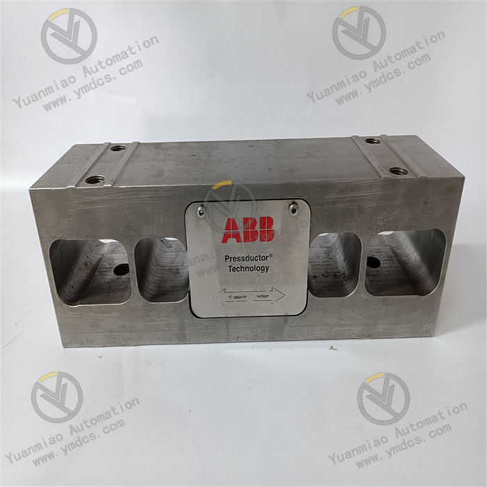
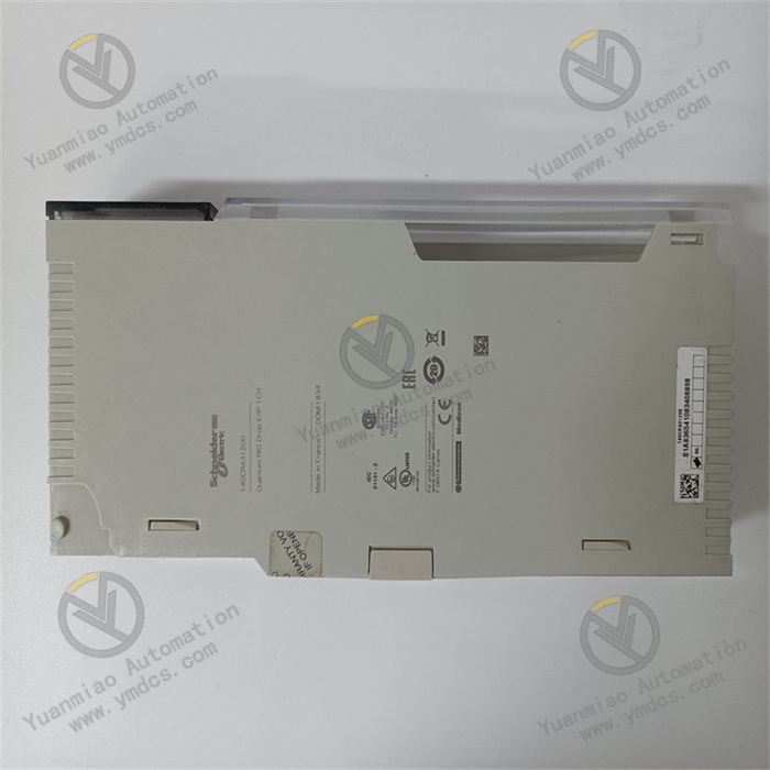
5SHX1060H0003
Basic Information: This is a reverse-conducting Integrated Gate-Commutated Thyristor (IGCT) produced by ABB for high-power applications, belonging to the semiconductor product series.
Structural Features: Compact in design, its wafer has two PN junctions forming two reverse diodes. Under forward polarity, it exhibits the conduction characteristics of a conventional thyristor with strong reverse-conducting capability.
Performance Advantages: Features low conduction voltage drop, low switching loss, and reverse blocking capability, facilitating easy assembly and installation.
Application Fields: Widely used in power converters, maglev trains, wind power generation, medium-to-high voltage frequency converters, and other fields, suitable for demanding applications such as wind turbines and marine propulsion systems.
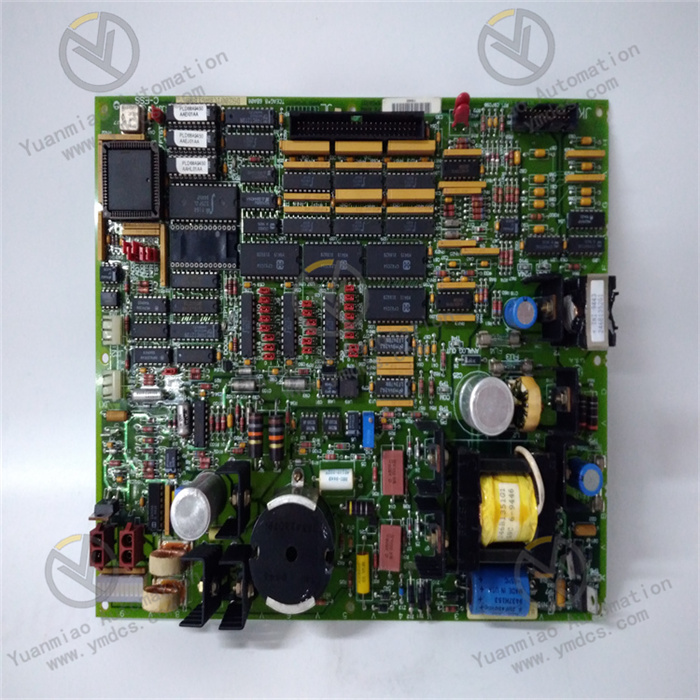
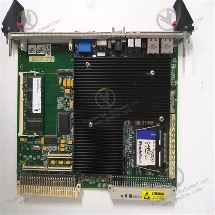
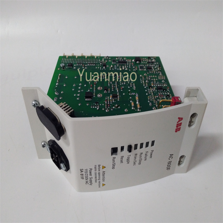
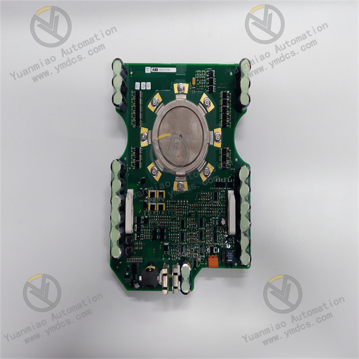
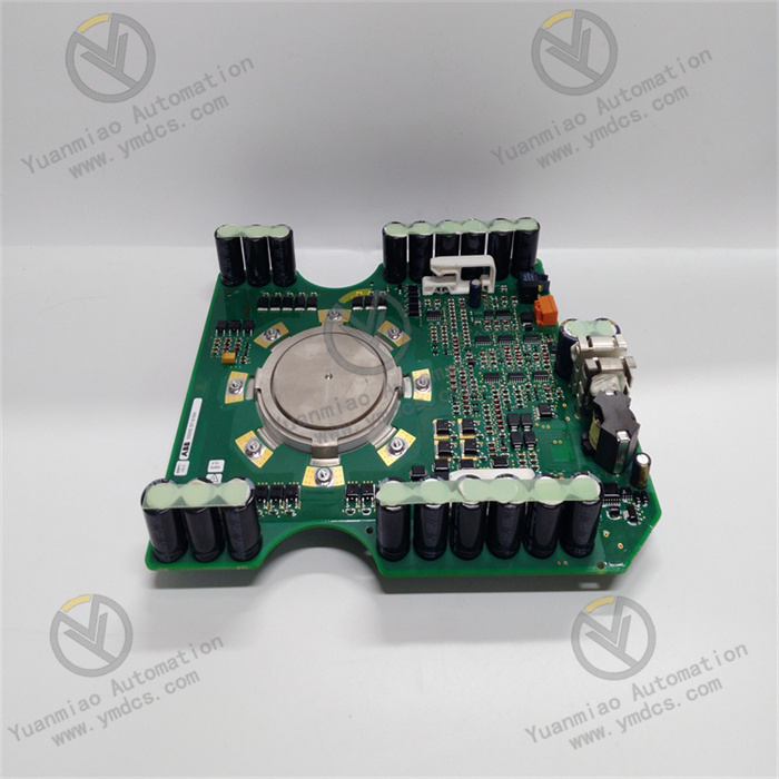
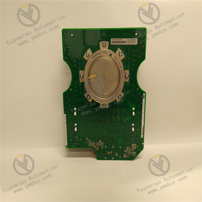
GVC714A101
Basic Information: This is an ABB silicon-controlled rectifier (SCR) module with the part number 3BHB020538R0001. However, there is currently limited publicly available technical information about this model.
Category: The SCR module, also known as a power semiconductor module, is a high-power semiconductor device with a modular package and a four-layer structure featuring three PN junctions.
Features and Applications: SCR modules are small in size, lightweight, compact, and highly reliable, with simple external connection lines, good interchangeability, and easy maintenance and installation. They can be used to control circuit frequency, phase, amplitude, voltage, current, and power, and are widely applied in power systems, power electronics, power automation, and other fields.
Working Principle of ABB IGCT 5SHX1060H0003
I. Device Positioning and Core Characteristics
IGCT (Integrated Gate-Commutated Thyristor) is a high-power semiconductor device that combines the high voltage/current withstand capability of thyristors with the gate-controllable characteristics of transistors. It is primarily used in high-voltage and high-power conversion scenarios (such as grid power transmission, industrial drives, renewable energy, etc.).
Model Analysis:
Model Analysis:
- 5SHX1060H0003:
- 5SHX: Prefix for ABB's IGCT series products.
- 1060: Represents the device's rated voltage and current class (typically 4500V/6300A level, specific parameters refer to the datasheet).
- H0003: Version or package code.
II. Physical Structure and Key Components
The core structure of IGCT is based on thyristor technology, but it achieves more flexible switching control through integrated gate drive circuits and optimized internal design. Its structure mainly includes:
- Semiconductor Chip:
- Composed of multi-layer silicon semiconductors (P-N-P-N structure), forming the basic conduction path of the thyristor.
- The chip surface integrates a gate (Gate) for receiving external control signals.
- Gate Drive Unit:
- Built-in drive circuit responsible for amplifying control signals to achieve fast injection and extraction of gate current.
- Includes auxiliary function modules such as voltage clamping and overcurrent protection.
- Packaging and Cooling System:
- Adopts a press-pack package to ensure reliable electrical connections between the chip and electrodes.
- Integrates water-cooling or air-cooling interfaces to dissipate heat during high-power operation (typical thermal resistance < 0.01 K/W).
III. Working Principle: The Full Process from Conduction to Turn-Off
The operating state of IGCT is controlled by gate signals, divided into three stages: conduction, sustained conduction, and turn-off. The core principles are as follows:
- Conduction Stage (Turn-On)
- After triggering by the gate current, a positive feedback mechanism forms inside the semiconductor:
- Once conducted, IGCT exhibits a low-impedance state (conduction voltage drop approx. 1.5–2.5V), allowing large currents (up to thousands of amperes) to pass through.
- Electrons are injected from the N layer into the P layer, and holes are injected from the P layer into the N layer, leading to full conduction of the multi-layer semiconductor.
- A forward voltage is applied between the anode and cathode (anode potential > cathode).
- A positive trigger current (pulse signal) is applied to the gate, injecting electrons into the P-N junction to initiate the thyristor's latch-up effect.
- Trigger Conditions:
- Physical Process:
- Sustained Conduction Stage (Conduction)
- High current density: Capable of withstanding continuous currents of thousands of amperes.
- Low conduction loss: Suitable for energy transmission in high-power scenarios.
- Once conducted, IGCT can maintain the conduction state without continuous gate signals (consistent with thyristor characteristics).
- The current magnitude is determined by the external circuit (e.g., load impedance, power supply voltage), and the gate loses control during this stage.
- Key Characteristics:
- Turn-Off Stage (Turn-Off)
- Gate commutation technology: Directly controls charge carrier recombination through gate current, avoiding the limitations of traditional thyristors relying on grid commutation.
- Snubber circuit: Works with an external RC-D circuit to suppress voltage spikes (dv/dt) during turn-off and protect the device.
- Gate extraction current rapidly reduces the charge carrier concentration in the P-N junction, breaking the latch-up effect.
- The device switches from a low-impedance conduction state to a high-impedance blocking state, completing the turn-off.
- A negative extraction current is applied to the gate to rapidly remove charge carriers (electrons and holes) from the semiconductor.
- The anode current decay rate must be lower than the device's allowable critical turn-off slope (di/dt) to avoid overvoltage breakdown.
- Core Difference: Unlike traditional thyristors, IGCT can be actively turned off by gate signals (traditional thyristors require external circuits to reduce the current to zero).
- Turn-Off Conditions:
- Physical Process:
- Key Technologies:
IV. Core Control Mechanism: Role of Gate Drive
The gate drive circuit of IGCT is the core feature distinguishing it from traditional thyristors, with main functions including:
- Trigger Pulse Generation:
- Provides forward pulses with steep edges (rise time < 1μs) to ensure fast conduction.
- Turn-Off Current Extraction:
- Applies high-amplitude negative current (up to hundreds of amperes) to accelerate charge carrier removal.
- Status Monitoring and Protection:
- Real-time monitoring of gate voltage, current, and chip temperature, triggering overcurrent and overheat protection logic.
- Synchronous Control:
- Supports precise synchronous triggering for series/parallel connected devices to avoid uneven voltage/current distribution.
V. Typical Application Scenarios and Operating Modes
IGCT 5SHX1060H0003 is commonly used in high-voltage frequency converters, flexible DC transmission (VSC-HVDC), large-capacity energy storage converters, etc. Its operating modes include:
- Voltage Source Converter (VSC) Mode:
- In HVDC systems, multiple IGCTs are connected in series to form a converter valve, enabling bidirectional conversion between AC and DC power.
- Gate signals are controlled by sinusoidal pulse width modulation (SPWM) or space vector modulation (SVM) strategies to generate high-precision AC voltage.
- Current Source Converter (CSC) Mode:
- In industrial drive systems (e.g., rolling mills, mine hoists), controls motor current and torque to achieve four-quadrant operation.
- Short-Circuit Protection Mode:
- Utilizes fast turn-off capability to quickly cut off fault current during grid faults, limiting short-circuit energy (I²t).
VI. Key Technical Advantages
- High Reliability:
- Press-pack packaging reduces lead inductance and mechanical stress, suitable for high-frequency switching (switching frequency up to 1–2kHz).
- Strong inrush current capability (peak current up to 10 times the rated current).
- High Efficiency and Energy Saving:
- Lower conduction loss than IGBTs (especially in high-voltage and high-current scenarios), suitable for megawatt-level power conversion.
- Flexible Control:
- Combines the high voltage resistance of thyristors with the controllability of transistors, eliminating the need for additional commutation circuits.

VII. Comparison with Other Devices
| Device Type | Conduction Method | Turn-Off Method | Typical Voltage/Current | Switching Frequency | Application Scenarios |
|---|---|---|---|---|---|
| IGCT | Gate-triggered | Actively turned off by gate | 4.5–6.5kV/kA level | 1–2kHz | High-voltage transmission, large-capacity conversion |
| Thyristor | Gate-triggered | Natural commutation (requires current zero-crossing) | Thousands of volts/kA level | Low frequency | Traditional HVDC, motor soft starting |
| IGBT | Gate-voltage controlled | Gate-voltage turned off | 600–1700V/kA level | 20kHz+ | Medium-low voltage frequency converters, new energy |
VIII. Safe Operation Precautions
- Drive Circuit Matching:
- Must use ABB's dedicated drive units (such as GVC714A101) to ensure compatibility of gate signal parameters (voltage, current, pulse width).
- Thermal Management:
- For forced water-cooling systems, maintain a flow rate ≥ 5L/min and inlet water temperature ≤ 40°C to avoid condensation or overheating.
- Overvoltage Protection:
- Parallel RC-D snubber circuits to limit dv/dt during turn-off (typically ≤ 1000V/μs).
- Series/Parallel Voltage Sharing:
- When connecting multiple devices in series, configure voltage-sharing resistors and capacitors to ensure voltage distribution unevenness < 5%.