Description
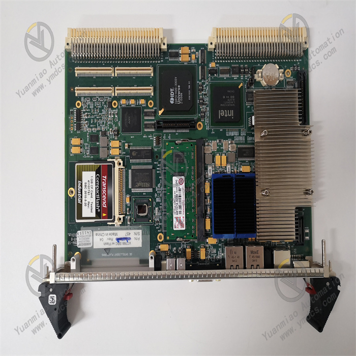
V7768-320001/350-9301007768-320001 A2
I. Overview
The Abaco Systems V7768-320001/350-9301007768-320001 A2 is a high-performance 6U single-slot VMEbus single-board computer (SBC), specifically designed to meet the rigorous demands of complex industrial automation, data acquisition, and communication fields. Integrating advanced technical concepts and reliable manufacturing processes, it is based on the mature VME (VersaModule Eurocard) bus architecture, presented in a modular form, demonstrating excellent stability and strong expandability. With its outstanding performance, it has played a key role in numerous industries since its launch, providing efficient data processing and control capabilities for various systems to support their stable operation. Since September 29, 2017, the product has entered the Restricted Production Phase (RPP), but it still maintains certain application value in the market due to its unique advantages.
II. Functional Features
(1) Powerful Processing Performance
Equipped with an Intel Core 2 Duo processor working in conjunction with the Intel 945GME high-speed chipset, it achieves a maximum processing speed of 2.16 GHz. This powerful combination endows the device with excellent computing capabilities, enabling it to quickly and accurately execute various complex control algorithms and data processing tasks. Whether it is real-time data analysis in industrial automation scenarios or massive data operations in communication systems, it can easily cope with them, providing a solid foundation for the efficient operation of the system.
(2) Abundant Memory Resources
Featuring up to 2GB of DDR2 SDRAM, it provides ample space for system operation and data storage. When facing multi-task parallel processing or handling large-scale data, it effectively avoids system 卡顿 (lag) or data loss caused by insufficient memory, ensuring that the system remains efficient and stable under complex workloads, thus improving overall work efficiency.
(3) Diverse I/O Interface Configuration
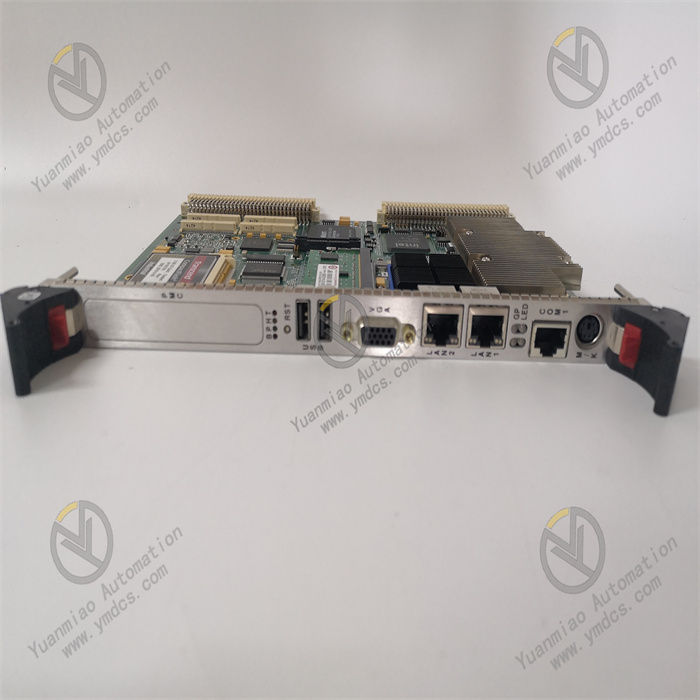
It offers a wide range of I/O interfaces, including dual Gigabit Ethernet interfaces to ensure high-speed and stable network communication for quick data interaction with other devices or networks; two SATA interfaces for convenient connection of large-capacity storage devices to meet data storage and reading needs; four USB 2.0 ports for easy access to external devices such as sensors and mobile storage; in addition, the front panel is equipped with keyboard/mouse/SVGA interfaces for users to perform local operations and display output. Meanwhile, it has a PCI-X compatible PMC expansion slot, providing the possibility for users to flexibly expand functional modules according to actual needs, which greatly enhances the device's versatility and adaptability, and can meet the connection and data transmission requirements with various devices in different application scenarios.
(4) Convenient Installation and Maintenance Design
Adopting the EasyRail PMC installation system, when only the "top" of the device is accessible for operation, the PMC option board can be easily installed. Access to PMC installation screws without disassembling the multi-slot carrier module significantly shortens the device configuration time, reduces maintenance difficulty, and improves device availability and maintenance efficiency. Even in environments with limited space, installation and maintenance can be conveniently completed, providing great convenience for users.
(5) Extensive Industry Adaptability
With its high performance, high reliability, and rich functional features, this product demonstrates strong adaptability in multiple industries. In the field of industrial automation, it can be used for production line control to precisely regulate production processes and improve production efficiency and product quality; in data acquisition, it can efficiently collect various sensor data to provide a reliable basis for subsequent analysis and decision-making; in communication systems, it can undertake data processing and forwarding tasks to ensure smooth communication; in aerospace, defense, and other fields with extremely high requirements for equipment performance and stability, it can also operate stably to provide strong support for critical tasks.
III. Working Principle
(1) System Startup and Power Supply
When the V7768-320001/350-9301007768-320001 A2 is connected to the VMEbus system and the external power supply is switched on, the internal power management module of the device immediately starts working. This module performs a series of conversion, voltage stabilization, and filtering processes on the input power, converting it into a stable voltage suitable for the normal operation of each component of the device, ensuring that components such as the processor, memory, and various interface circuits can obtain stable and adaptive power supply, thereby ensuring the device starts smoothly and operates continuously and stably.
(2) Data Processing Flow
In the data processing process, when the system receives an external data processing task instruction, the Intel Core 2 Duo processor first parses and calculates the task according to preset programs and algorithms. The processor's powerful computing capability enables it to quickly process complex logical operations and data manipulations. For example, in industrial automation control, it analyzes a large amount of real-time data collected by sensors, judges the operating status of production equipment, and generates corresponding control instructions. During the operation process, the processor frequently interacts with the 2GB DDR2 SDRAM, reading the required data from the memory and timely storing the operation results back into the memory to ensure the continuity and efficiency of data processing.
(3) Data Transmission Mechanism
The device's rich I/O interfaces play a key role in data transmission. Taking network data transmission as an example, when data interaction with the external network is required through the dual Gigabit Ethernet interfaces, the network data first enters the Ethernet controller. After protocol parsing and data encapsulation, it is transmitted to the processor for processing through the VMEbus. The processed result data then follows the reverse process, is encapsulated into data packets conforming to network protocols by the Ethernet controller, and sent to the external network. For other interfaces, such as when the SATA interface is connected to a storage device for data reading and writing, data is orderly transmitted between the device and the storage device through the corresponding interface controller and VMEbus to ensure the accuracy and efficiency of data transmission. The entire process strictly follows the VMEbus protocol to ensure smooth data communication between devices.
IV. Operation Guide
(1) Pre-installation Preparations
- Compatibility Confirmation: Before proceeding with the installation, carefully verify the detailed specifications of the target VMEbus system. Focus on key information such as the type, quantity, electrical characteristics, and available power of the VMEbus slots to ensure full compatibility with the V7768-320001/350-9301007768-320001 A2. An incompatible system may lead to installation failure or even device damage, so compatibility confirmation is a crucial step before installation.
- Tool Preparation: Prepare necessary installation tools, such as anti-static wristbands and screwdrivers of suitable sizes. During operation, be sure to wear an anti-static wristband to prevent static electricity generated by the human body from damaging the sensitive electronic components inside the device and ensure the safety of the installation process.
(2) Module Installation
- Chassis Opening: Carefully open the VMEbus system chassis and find a suitable 6U single-slot position inside the chassis to prepare for installing the V7768-320001/350-9301007768-320001 A2 module.
- Module Insertion: Hold the V7768-320001/350-9301007768-320001 A2 module, precisely align the interface at the bottom of the module with the VMEbus slot, keep the module in a vertical state, and insert the module into the slot smoothly and slowly. During the insertion process, pay attention to moderate force to avoid bending or damaging the interface pins until the module is fully inserted and fixed firmly.
- Module Fixing: Use a screwdriver to tighten the fixing screws on both sides of the module one by one to ensure that the module is firmly installed in the chassis without shaking or loosening, providing a solid physical guarantee for the stable operation of the device.
(3) Device Connection
- Network Connection: If the dual Gigabit Ethernet interfaces need to be used for network communication, prepare suitable Ethernet cables, connect one end to the device's Ethernet interface, and the other end to the target network device, such as a switch or router, to ensure the stability and reliability of the network connection.
- Storage Device Connection: If connecting to a SATA storage device, such as a hard disk, prepare SATA data cables and power cables. Connect one end of the SATA data cable to the device's SATA interface and the other end to the hard disk's SATA interface; at the same time, correctly connect the power cable to the hard disk to provide power for the hard disk and realize the data transmission and storage function between the device and the storage device.
- Other Device Connections: According to actual needs, use corresponding cables to connect USB devices, keyboards, mice, monitors, etc., to the corresponding interfaces of the device. For example, insert USB devices into the USB 2.0 ports, connect keyboards and mice to the corresponding interfaces on the front panel, and connect monitors to the SVGA interface to complete the connection work between the device and external devices.
(4) System Startup and Operation
- System Startup: After completing all device connections, close the VMEbus system chassis and turn on the system power. The device will start up. During this process, pay attention to observing the status of the device's indicator lights. Under normal circumstances, the indicator lights will turn on or flash in a specific order, indicating that the device is undergoing self-checking and other startup processes.
- System Login and Operation: After the device starts up, enter the correct username and password in the corresponding login interface according to the operating system used for login. After successful login, you can use the device's various functions for data processing, control operations, etc., through the operating system or related application programs. For example, in industrial automation applications, production equipment can be remotely monitored and controlled through corresponding control software; in data acquisition applications, a data acquisition program can be started to begin collecting and storing various sensor data.
(5) Common Fault Troubleshooting
- Device Fails to Start: Check whether the power connection is secure and confirm whether the external power supply is normally supplying power; check the status of the device's indicator lights. If the indicator lights do not turn on or display abnormally, it may be a fault in the device's internal power module, and professional technical personnel should be contacted for maintenance.
- Network Connection Failure: Check whether the Ethernet cable connection is loose and try to reinsert the cable; confirm whether the network device (such as a switch) is working normally; in the device's operating system, check whether the network configuration is correct, such as whether the settings of IP address, subnet mask, etc., are incorrect, and the network connectivity can be tested through the ping command.
- Data Transmission Error: If errors occur during data transmission, such as data loss or abnormally slow transmission speed, check whether the connection cable is damaged and try to replace the cable; confirm whether the interface driver between the device and the connected device is correctly installed and is the latest version, and the driver can be downloaded and updated from the device manufacturer's official website; for data transmission problems of storage devices, check whether the storage device has faults such as bad sectors, and relevant tools can be used for detection and repair.