Description
GE Multilin SR469-P5-HI-A20-E
I. Overview
The GE Multilin SR469-P5-HI-A20-E is a multifunctional motor management relay belonging to GE Multilin's SR469 series. With shared design features and compatibility, this series excels in motor protection and control. Specifically engineered for industrial applications, this model aims to provide comprehensive protection and precise monitoring for the operational status of medium to large motors. It plays a critical role in various fields such as industrial automation, power systems, pumping stations, fans, conveyors, machine tools, and compressors, serving as a reliable device to ensure the safe and stable operation of all types of motors.
II. Functional Features
Comprehensive and Precise Protection System
Equipped with diverse protection functions to safeguard motors comprehensively:
- Overload Protection: Sensitive to prolonged overloading of motors, taking timely measures to prevent damage from overheating.
- Short-Circuit Protection: Instantly cuts off excessive current caused by short-circuit faults to prevent irreversible equipment damage.
- Undervoltage Protection: Effectively addresses low voltage issues, avoiding motor malfunction or burnout due to insufficient voltage.
- Phase Sequence Protection: Identifies incorrect power phase sequences to prevent accidents caused by motor reverse rotation.
- Additional functions may include overvoltage protection and temperature protection, ensuring all-around protection for motor operation.
High-Precision Parameter Measurement
Accurately measures key parameters such as current, voltage, frequency, and power, providing reliable data support for evaluating motor operation status. These high-precision measurements are invaluable for real-time monitoring, fault troubleshooting, and analysis.
Intelligent Thermal Capacity Management
Supports thermal capacity management to effectively handle unbalanced bias issues. Through real-time monitoring and analysis of the motor's thermal status, it adjusts operating parameters reasonably to avoid motor failures due to thermal accumulation or imbalance, extending motor service life.
Flexible and Convenient Communication Capability
Supports multiple communication protocols (RS232, RS485, Ethernet) and is compatible with common communication standards (Modbus, Profibus, IEC 61850), facilitating integration with various automation systems. These interfaces enable seamless remote data transmission, real-time monitoring, and control, allowing maintenance personnel to access motor status anytime and address potential issues promptly.
Simple and User-Friendly Operation Interface
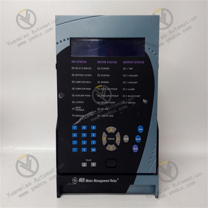
Features an enhanced front panel design with a sealed pull-out handle, simplifying installation/maintenance and preventing misoperations. The front panel includes clear LED indicators, a 40-character LCD display, communication ports, and operation buttons, enabling operators to visually check motor parameters, fault information, and protection status, and easily configure parameters or select functions via buttons.
Excellent Reliability and Durability
Constructed with high-quality materials and advanced manufacturing processes for superior reliability and durability. Some models incorporate special designs for harsh environments (e.g., protective coatings) to resist corrosion, hydrogen sulfide, high humidity, etc., ensuring stable operation in complex conditions and reducing maintenance costs.
III. Technical Parameters
- Rated Voltage: Supports 90-300 VDC or 70-265 VAC control power, adapting to different power system requirements.
- Rated Current: Available in specifications like 5A or 1A to match various motor load currents.
- Phase CT Secondary Coil: Commonly 5A for accurate current signal acquisition.
- Input Ports: 5 analog and digital input channels for connecting multiple sensors and control signals.
- Output Ports: 2 analog output channels (e.g., 4-20mA) for signal transmission and control with external devices.
- Maximum Load Current: Up to 2A to meet certain load driving requirements.
- Operating Frequency: 48-62Hz, suitable for power frequency standards in most regions worldwide.
- Protection Rating: Some models reach IP54 (dustproof and water splash-proof); others are IP20 for general indoor environments.
- Communication Interfaces: Supports RS232 (baud rate programmable up to 19200), RS485, Ethernet, etc., for data interaction with host computers or other devices.
- Operating Temperature: General range: -20°C to 60°C; specially designed models: -40°C to +85°C.
- Humidity: Adapts to non-condensing environments with relative humidity up to 90%.
- Dimensions: Approximately 200mm x 165mm x 80mm (may vary slightly by product).
- Weight: Approximately 2.2 kg for easy installation and handling.

IV. Working Principle
The SR469-P5-HI-A20-E real-time collects current and voltage signals from each motor phase via built-in current transformers (CT) and voltage transformers (VT). These signals are transmitted to the internal microprocessor system, which performs high-speed calculations and analysis based on preset protection algorithms and logic.
- Example: Overload Protection: When monitored current continuously exceeds the motor's rated current by a certain multiple and lasts for the preset overload action time, the microprocessor determines an overload and issues control signals to activate corresponding relays, cutting off power or reducing load.
- Short-Circuit Protection: Upon detecting a sudden surge in current exceeding the short-circuit protection threshold, the microprocessor rapidly issues a trip command to cut off the circuit and prevent severe damage from excessive current.
- Phase Sequence Protection: Analyzes voltage phase relationships to determine correct power phase sequence. If incorrect, it immediately outputs control signals to block motor startup and prevent hazards from reverse rotation.
Additionally, the device calculates real-time parameters (power, frequency, etc.) from collected current/voltage data and uploads them to the monitoring system via communication interfaces, enabling comprehensive monitoring and management of motor operation.

V. Operation Guide
Local Operation
- Startup and Initialization: After powering on, the relay performs self-check and initialization (front-panel LED indicators flash, LCD displays self-check information). Upon completion, the display shows real-time motor parameters (current, voltage, etc.).
- Menu Operation: Press the front-panel "Menu" button to enter the main menu (including "Settings," "Monitoring," "Fault Records," etc.). Use up/down arrows to select options and "Enter" to access submenus.
- Parameter Configuration: In "Settings," select submenus like "Motor Parameters," "Protection Settings," "Communication Settings." For example, set motor rated power/current/voltage in "Motor Parameters," or adjust overload trip current multiples/time, short-circuit trip thresholds in "Protection Settings." Enter values via numeric keys and confirm with "Enter."
- Monitoring Function: In "Monitoring," view real-time parameters (three-phase current/voltage, power, frequency) and motor status (running, stopped, fault, etc.).
- Fault Record Inquiry: The device automatically logs faults. In "Fault Records," view details (fault type, time, parameters at fault) for troubleshooting.
- Exit Operation: Press "Exit" to return to upper menus step-by-step until exiting the menu interface.
Remote Operation
- Communication Connection: Ensure correct wiring and matching communication parameters (baud rate, address, IP, etc.) for RS485, Ethernet, or other connections.
- Monitoring Software Operation: Open the host monitoring software, locate the SR469-P5-HI-A20-E in the device list, double-click or select "Connect" to establish communication. The interface displays real-time parameters/status similar to local "Monitoring."
- Remote Parameter Configuration: Access the parameter settings interface in the software to remotely configure motor/protection/communication parameters (similar to local menu operations). Note authority management to ensure safety/accuracy, then save/apply settings to the device.
- Remote Control: Some software supports remote motor control (start/stop/reverse, etc.). Click corresponding buttons on the interface to send commands, but ensure on-site safety during operation.