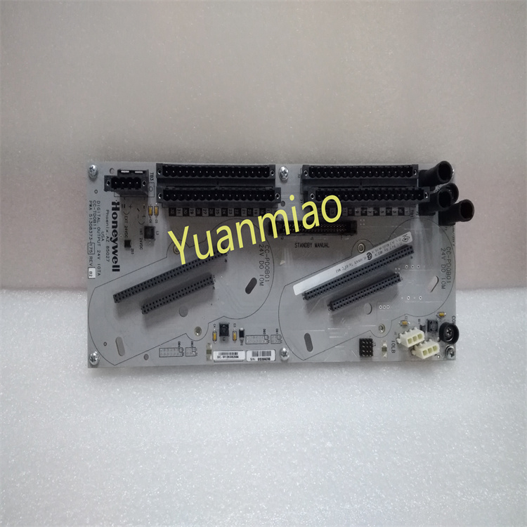
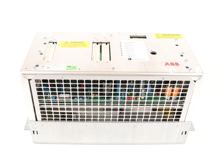
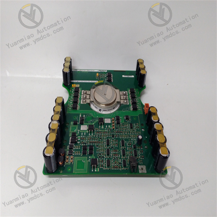
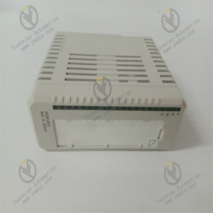
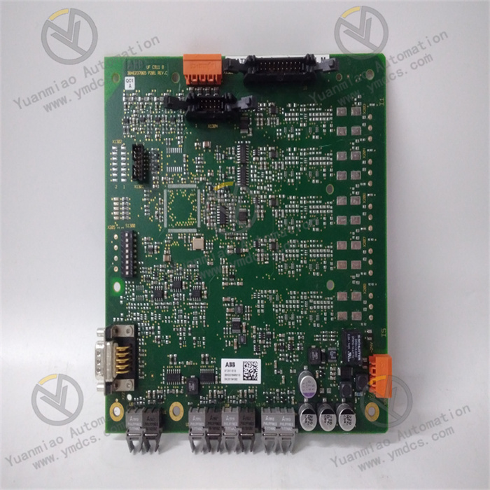
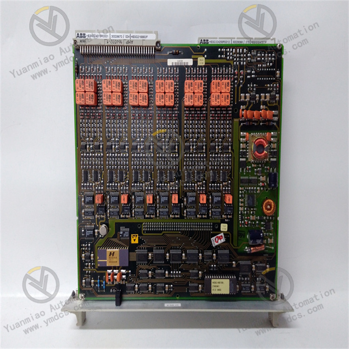
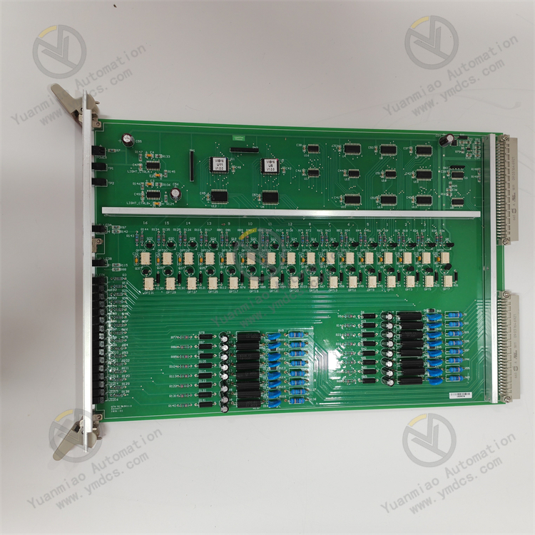
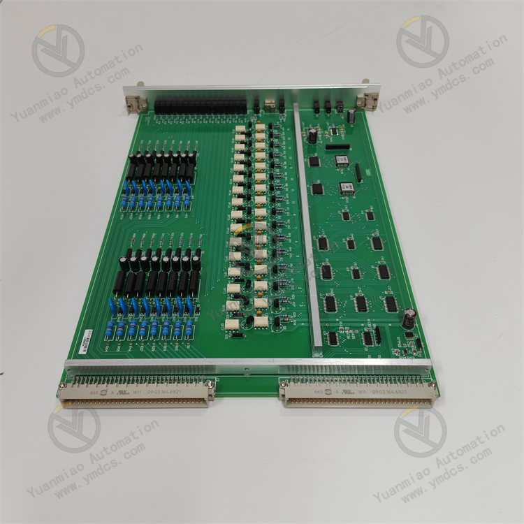
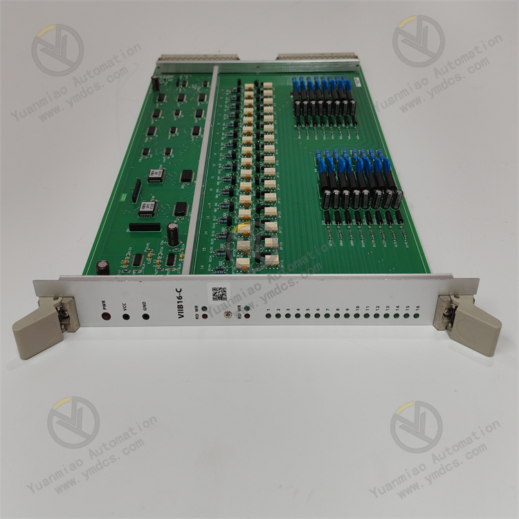
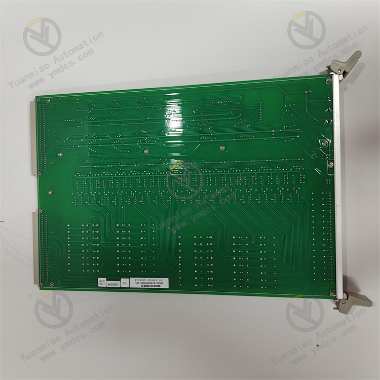
Description
Technical Parameters:
- Power Supply Parameters
- Rated Voltage: Typically DC 24V, allowing a certain voltage fluctuation range, such as DC 24V±10%.
- Power Consumption: Generally between several watts and tens of watts, specifically depending on the module's functions and the number of channels.
- Input Characteristics
- Input Type: Digital input, capable of receiving switch signals (e.g., 0V/24V indicating off/on), discrete signals from sensors, etc.
- Number of Input Channels: Common configurations include 8 channels, 16 channels, 32 channels, etc. The STO1726KO1 module may have one of these channel configurations.
- Input Signal Voltage Range: For DC input, generally DC 15V–30V is recognized as high level (logic "1"), and DC 0V–5V is recognized as low level (logic "0").
- Input Impedance: Typically between several kilohms and tens of kilohms to ensure correct acquisition of input signals and avoid excessive loading on external signal sources.
- Filter Time Constant: Adjustable filter times (e.g., 1ms, 10ms, 100ms, etc.) are available to filter out high-frequency interference pulses in input signals and improve signal stability.
- Communication Interface Parameters
- Communication Protocols: May support multiple protocols such as CANopen, MVB, Profibus-DP, Ethernet/IP, etc., to communicate with train control systems (e.g., PLC, TCMS).
- Communication Rate: Varies by protocol. For example, common CANopen rates include 125Kbps, 250Kbps, 500Kbps; MVB typically operates at 1.5Mbps.
- Communication Address: The slave address of the module can be set via hardware DIP switches or software configuration to ensure a unique identifier in the communication network, allowing the master station to correctly address and interact with the module.
- Electrical Isolation Parameters
- Inter-Channel Isolation: Input channels are usually electrically isolated to prevent signal interference between channels, with isolation voltages ranging from hundreds to thousands of volts (e.g., 500V, 1000V, 2500V, etc.).
- Input-Power Isolation: Isolation is also provided between the input circuit and the power circuit to protect the module and external devices from power fluctuations and interference, with isolation voltages typically equivalent to or higher than inter-channel isolation voltages.
- Input-Communication Isolation: Isolation between the input section and the communication interface ensures the stability and reliability of communication signals, preventing electrical interference from the input side from affecting communication, with isolation voltages also in the hundreds to thousands of volts range.
- Mechanical and Environmental Parameters
- Mounting Method: Generally rail-mounted or screw-mounted for easy fixing in control cabinets or equipment racks.
- Dimensions: Vary depending on the number of channels and functional complexity, typically ranging from tens to hundreds of millimeters. For example, length×width×height may be approximately 100mm×80mm×50mm.
- Operating Temperature Range: Typically -25°C to +70°C or a wider range to adapt to different environmental temperatures and ensure stable module operation in various train operating environments.
- Humidity Range: Capable of adapting to a certain humidity environment, such as 5%–95% relative humidity (non-condensing).
- Vibration and Shock Resistance: Meets relevant standards in the rail transit industry, such as withstanding vibrations of certain frequencies and accelerations (e.g., 10Hz–500Hz, 2g–5g) and shocks of certain intensities (e.g., 10g–30g, lasting several to tens of milliseconds) to ensure reliability during train operation.
Features
- High Reliability: Adopts redundant design, fault-tolerant mechanisms, and high-quality electronic components to ensure long-term stable operation in harsh environments, reducing failure rates and guaranteeing continuous system operation.
- Rich Interfaces: Provides multiple standard interfaces (e.g., Ethernet, serial ports, CAN bus) to facilitate connection with train control systems, signaling systems, monitoring systems, etc., enabling information sharing and collaborative operation.
- High-Precision Signal Acquisition: Equipped with high-precision analog input channels to accurately collect weak signals from various sensors and perform precise analog-to-digital conversion and digital signal processing, providing accurate data support for train control and protection.
Common Faults
- Power and Physical Connection Faults
- No Power to Module: May be caused by external power supply failures (e.g., unstable voltage, reverse polarity, blown fuse); loose or poor power terminal connections or incorrect wiring; internal power circuit damage (e.g., swollen capacitors, burnt chips).
- Module Overheating or Abnormal Heating: May be due to poor ventilation in the installation environment, dust-blocked cooling holes; long-term operation beyond the rated temperature range; or aging/short-circuiting of internal components.
- Communication and Data Transmission Faults
- Communication Interruption: May result from loose, broken, or poorly shielded/grounded communication bus cables; communication address conflicts or parameter configuration errors; or faulty communication chips/abnormal firmware.
- Data Transmission Errors or Loss: May be caused by electromagnetic interference affecting bus signals; excessive communication cable length or lack of shielded cables leading to signal attenuation; or internal communication buffer errors/hardware failures.
- Input Channel Function Abnormalities
- Single or Multiple Unresponsive Input Channels: May be due to external signal source failures; loose, short-circuited, or overloaded input terminals; or internal channel circuit damage.
- False Input Signal Triggers: May result from inductive voltage or crosstalk in external lines; improper module input filter parameter settings; or reduced channel insulation causing leakage current false triggers.
- Mechanical and Environmental Faults
- Module Loose or Poor Contact: May be caused by untightened mounting screws, causing the module to detach from the backplane or rail in vibrating environments; or oxidized, bent, or broken connector pins leading to electrical connection failures.
- Faults Caused by Environmental Stress: Long-term vibration may cause internal component solder joint failures; humid environments may cause circuit board corrosion or reduced insulation; contaminants such as salt spray or dust entering the module may cause short circuits or poor contact.
Application Fields and Functional Directions of ALSTOM STO1726KO1 Module:
I. Rail Transit Field
Alstom's modules in rail transit are commonly used in train control, signaling systems, vehicle electrical management, etc. The STO1726KO1 may be involved in the following applications:
- Train Control System (TCMS)
- Connects to sensors (e.g., speed sensors, pressure sensors) to monitor train operation parameters in real time.
- Controls actuators (e.g., relays, solenoids) to automate door, air conditioning, and lighting systems.
- Function: As a node module in the train communication network (e.g., MVB, WTB, CANopen), it collects vehicle status data (e.g., door switches, braking status, traction motor parameters) and communicates with the train's central control unit (CCU).
- Scenarios:
- Signaling Systems and Wayside Equipment
- Communicates with ground signal lights, axle counters, balises, etc., to ensure trains operate safely according to signaling instructions.
- Supports train tracking, route control, and collision avoidance functions in metro, high-speed rail, or mainline railway systems.
- Function: As a wayside signaling module, it participates in automatic train operation control (e.g., ATP/ATO systems), processing track circuit signals, switch statuses, train position verification, etc.
- Scenarios:
- Vehicle Electrical System Management
- Controls the start/stop and parameter adjustment of traction converters and auxiliary power supplies (e.g., inverters, batteries).
- Monitors electrical system parameters (voltage, current, temperature, etc.) and triggers overload protection or fault alarms.
- Function: Manages power supply, load control, and fault diagnosis for train electrical equipment to ensure stable operation of the electrical system.
- Scenarios:
- Fault Diagnosis and Safety Circuits
- Collects safety signals from emergency brake buttons, fire detectors, etc., to directly trigger safety braking actions.
- Meets the reliability requirements of EN 50155 (rail transit electronic equipment standards) through redundant design and fault detection mechanisms.
- Function: Integrates safety-related digital input/output channels to build train safety circuits (e.g., emergency braking circuits), ensuring rapid response to faults.
- Scenarios:
II. Industrial Automation and Energy Field
Some Alstom modules can also be applied to industrial scenarios, especially those requiring high reliability and anti-interference capabilities:
- Power and Energy Equipment Control
- Connects to PLC or DCS systems to collect power parameters (e.g., voltage, frequency) or control the start/stop of power equipment.
- Participates in unit status monitoring and grid connection control in renewable energy fields such as wind and hydropower.
- Function: As an expansion module for industrial controllers in power plants, substations, or energy storage systems, it monitors and controls switching equipment, valves, and instruments.
- Scenarios:
- Industrial Machinery and Process Control
- Controls the operation of robotic arms and conveyor belts in manufacturing, or collects equipment status data (e.g., temperature, vibration).
- Integrates with industrial networks through standardized interfaces (e.g., Profibus, EtherCAT) to enable collaborative operation of distributed control systems (DCS).
- Function: As an input/output module for industrial automation systems, it supports logical control or data collection for production line equipment.
- Scenarios: