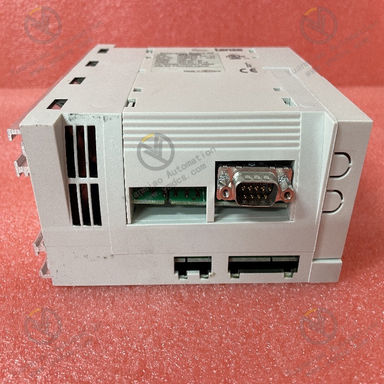
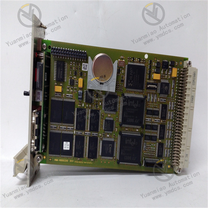
Description
DS215DMCBG1AZZ03A
I. Overview
The DS215DMCBG1AZZ03A is a circuit board module specifically developed by General Electric (GE) for the Mark V series steam turbine control system. This module undertakes crucial tasks such as drive control, providing strong support for the stable operation of the steam turbine control system. Although the Mark V series is an obsolete product line that has been discontinued, it is still highly praised in the automation industrial market due to its advanced technology and excellent performance. Its application scope mainly focuses on the control of gas and steam turbine systems, playing an important role in industries such as energy and power.
II. Functional Features
- High Reliability: Having undergone strict quality control processes and environmental adaptability tests, it can operate stably in harsh industrial environments such as high temperature, high humidity, and strong electromagnetic interference. This significantly reduces downtime caused by failures and ensures the continuity of production.
- Flexible Communication Capability: It supports multiple application protocols such as SRTP and Modbus TCP/IP, and has built-in Ethernet user support communication functions. This enables convenient data interaction with other devices and systems, meeting communication requirements in different scenarios.
- Easy Maintenance: It provides user-friendly programming interfaces and tools, making it convenient for technicians to perform programming, debugging, and daily maintenance work. This reduces the difficulty and cost of maintenance and improves maintenance efficiency.
- High-performance Processing Capacity: Adopting advanced processor and communication technologies, it has scalable processing capabilities. It can not only transmit and process data quickly and stably, but also allows users to create powerful systems according to actual needs. Moreover, software changes are not required during subsequent upgrades, demonstrating good scalability and forward - looking nature.
- Support for Multiple Fieldbus Interfaces: It has multiple fieldbus interfaces, providing support for distributed control and/or I/O. This facilitates the construction of complex and efficient control systems and enables precise control of industrial production processes.
- Rich Programming Language Support: It can be programmed through Proficy Logic Developer PLC Machine Edition and supports multiple programming languages such as Ladder Diagram (LDI), Instruction List (IL), Structured Text (ST), and C blocks. This is convenient for engineers with different programming habits to carry out development work.
- Low Cost and High Availability: As a low-cost solution, it is equipped with redundant CPUs and power supplies, which can be used to build high-availability solutions. This effectively controls cost investment while ensuring system performance.
III. Technical Parameters
- Manufacturer: General Electric (GE)
- Series: Mark V
- Product Type: DMC BG 1 & FW
- Functional Abbreviation: DMCB
- PCB Coating: Ordinary coating
- Functional Version: 1A
- Drawing Version: Z
- Rated Power: No clear information (it can be speculated with reference to similar modules, and it may be within the range that meets the control requirements of steam turbines, such as the 5, 10, and 22 kilowatt specifications mentioned previously for related modules)
- Electrical Parameters:
- Operating Voltage: 18.5 to 36Vdc
- Output Voltage: No clear information on output voltage (if used for signal control, it may output a level that conforms to digital signal logic; if it involves power driving, the output voltage needs to be adapted to the driven device, and the speculated range is wide, which needs to be determined according to the actual application scenario)
- Output Current: No clear information on output current (similarly, it varies according to different driven loads. For example, if driving small relay - like components, the current is small; if driving high-power equipment, the current is large)
- Physical Characteristics:
- Dimensions: 84x160x110mm
- Weight: 1.29Kg
- Environmental Parameters:
- Ambient Temperature: 5 to 55°C
- Ambient Humidity: 0% - 95% non-condensing
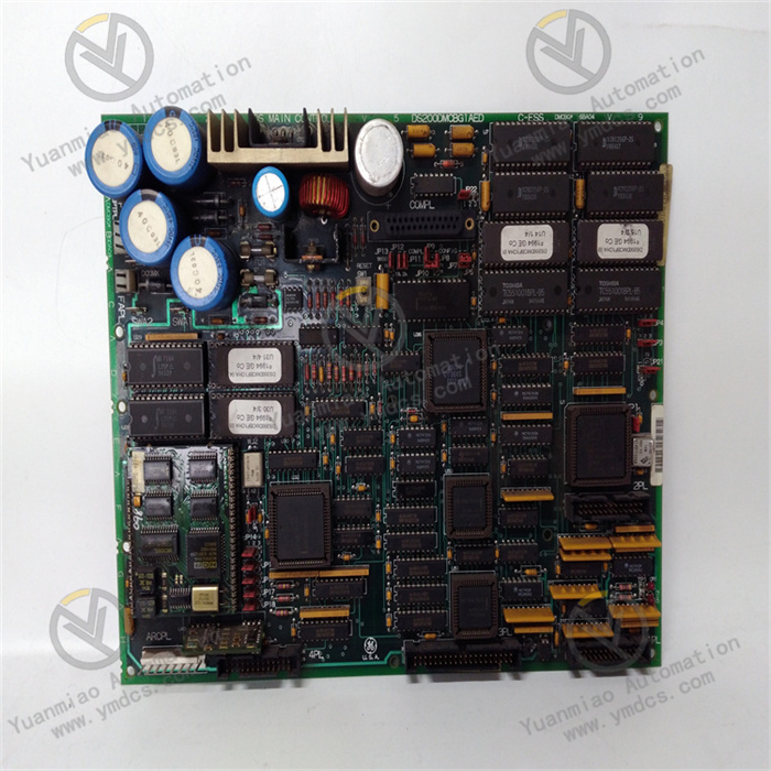
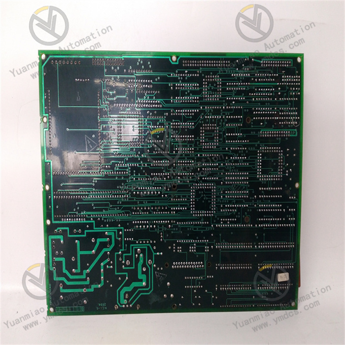
- Hardware Composition:
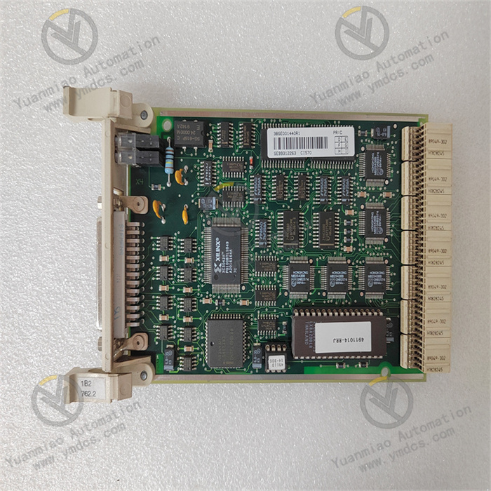
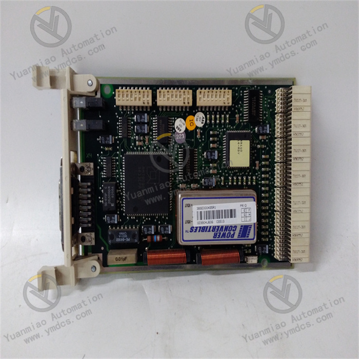
- Connectors: It has five vertical cable connectors, including four male connectors and one female connector; three vertical plug connectors; three stab - on connectors.
- Auxiliary Boards: It is equipped with two auxiliary boards, one installed vertically and one horizontally, both located at the lower left corner.
- Other Components: It is equipped with more than twenty jumper switches, a reset switch located in the upper left quadrant, LED indicators, an inductance coil, TP test points for checking the board voltage, more than fifty-five integrated circuits (including oscillation chips, field - programmable gate arrays, and eprom chips for data storage), and multiple fuse components. It also uses resistor network arrays, transistors, and various capacitors, diodes, and resistors. Letters, alignment marks, and grooves for alignment are marked along the two edges of the board, and there are additional drilled holes at the corners, center, and edges of the board.
IV. Working Principle
Although there is currently no publicly available detailed information explaining the specific working principle of the DS215DMCBG1AZZ03A, a reasonable speculation can be made based on its functions in the Mark V steam turbine control system and the working mechanisms of similar modules. This module most likely conditions and converts the input electrical signals through its internal circuit design to provide a stable and compliant power supply for other parts of the steam turbine control system. At the same time, with the help of advanced processor and communication technologies, it conducts real-time monitoring and precise control of the steam turbine's operating status according to the preset control logic and received external signals. In terms of data transmission, it utilizes multiple supported communication protocols to achieve data interaction with other devices and systems, thereby achieving coordinated control of the entire steam turbine system and ensuring the safe and efficient operation of the steam turbine.
V. Common Faults and Solutions
- Power Failure
- Fault Phenomenon: The module fails to start, or it operates unstably after startup, such as restarting without any reason.
- Possible Causes: Abnormal input power voltage, such as being too high, too low, or fluctuating greatly; loose, poor - contact, or open - circuit power connection cables; faults in the internal power circuit of the module, such as blown fuses or damaged power chips.
- Solutions: First, use tools such as a multimeter to check whether the input power voltage is within the specified range of 18.5 to 36Vdc. If the voltage is abnormal, check the power supply system, such as whether power transformers, voltage regulators, and other equipment are working normally. Then, check the power connection cables to ensure they are firmly connected without any signs of looseness or damage. If there are problems, re - insert or replace the connection cables. If the above checks are normal, it may be a fault in the internal power circuit of the module. In this case, professional technicians are required to use professional equipment such as oscilloscopes and logic analyzers to detect the internal circuit of the module, identify the faulty components, and replace them, such as replacing the damaged fuses or power chips.
- Communication Failure
- Fault Phenomenon: The module is unable to communicate normally with other devices, such as being unable to receive or send data, or experiencing packet loss and errors during data transmission.
- Possible Causes: Incorrect connection of the communication interface, such as loose or poor - contact interfaces, or the use of mismatched communication cables; incorrect communication parameter settings, such as inconsistent baud rate, data bits, stop bits, parity bits, etc., with other devices; faults in the internal communication chip or circuit of the module.
- Solutions: Carefully check the connection of the communication interface to ensure that the interface is tightly connected and the communication cables are correctly connected and undamaged. If the connection is correct, check the communication parameter settings, compare the communication parameters of the module with those of other devices it communicates with, and ensure they are consistent. If communication is still not possible after the parameter settings are correct, it may be a fault in the internal communication chip or circuit of the module. Professional personnel are required to disassemble and detect the module, use professional instruments to determine whether the communication chip is damaged, and replace it if it is; if the communication chip is normal, further check the circuit lines to repair open - circuit and short - circuit problems.
- Hardware Failure
- Fault Phenomenon: Some components on the module are damaged, such as burned - out chips, bulging capacitors, open - circuit resistors, etc., resulting in abnormal module functions, such as inability to drive devices normally or incorrect control signal output.
- Possible Causes: Long - term operation in harsh environments, such as high temperature, high humidity, strong electromagnetic interference, etc., leading to component aging, performance degradation, or even damage; the module is impacted by overvoltage and overcurrent during use, causing component damage; problems with the quality of the components themselves.
- Solutions: For components with obvious signs of damage, such as burned - out chips and bulging capacitors, they can be directly replaced. For component faults that cannot be judged by appearance, such as open - circuit resistors and poor - performing transistors, tools such as multimeters and oscilloscopes are required for detection. When replacing components, select components with the same model and specifications as the original ones, and ensure good soldering techniques to avoid problems such as cold soldering and short circuits. At the same time, if environmental factors are suspected to be the cause of the hardware failure, the working environment of the module should be improved, such as strengthening heat dissipation, taking moisture - proof measures, and increasing electromagnetic shielding.
- Software Failure
- Fault Phenomenon: The module operates abnormally, but no problems are found during hardware inspection. It is likely that there are errors in the software program, such as program runaway, data loss, etc., resulting in the module being unable to work according to the preset logic.
- Possible Causes: Errors occurred during the programming and debugging process, resulting in loopholes in the software program; the module is affected by factors such as electromagnetic interference during operation, causing the program to malfunction; the software version is too old, resulting in compatibility problems.
- Solutions: First, try to reset the module to see if it can return to normal operation. If the reset is ineffective, use professional programming tools to check and debug the software program of the module, find and fix the errors in the program. If the software version is suspected to be the problem, contact GE's official to obtain the latest software version and follow the official instructions for the upgrade operation. During the upgrade process, pay attention to backing up the original data to prevent data loss. At the same time, to avoid the recurrence of software failures, fault - tolerant processing and anti - interference measures can be added to the software, such as data verification and watchdog timers.