Description
1. Product Overview
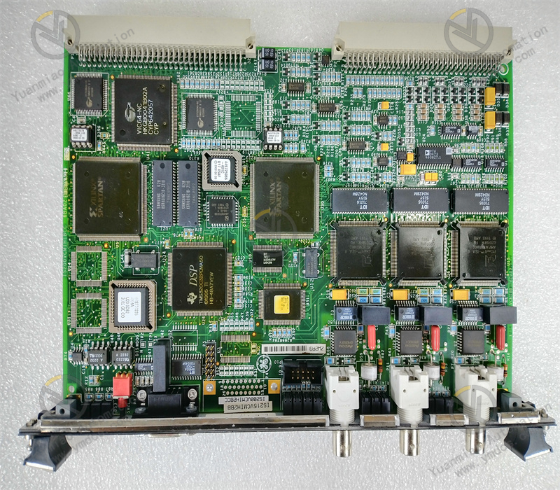
GE IS215VCMIH2CB is a VME‑architecture main controller board (VME Control Module / CPU Board) belonging to GE Speedtronic Mark V turbine control system. It serves as the core computing and scheduling hardware for Mark V gas‑turbine and steam‑turbine control systems. Designed based on VMEbus industrial standard bus architecture, this board is developed for TCS (Turbine Control System), TSI (Turbine Supervisory Instrumentation) and generator control systems of GE gas turbines, steam turbines, hydro‑turbine units and centrifugal compressor units. It undertakes central‑processing tasks including turbine control logic computation, I/O data acquisition and management, redundant communication scheduling, system self‑diagnosis and VME bus backplane control, acting as the “main CPU” hardware responsible for overall unit coordination, algorithm execution and redundancy management within Mark V control systems.
It has passed comprehensive industrial‑grade tests including full‑load power‑on aging, temperature cycling, vibration‑shock test, dielectric withstand, electromagnetic interference test and long‑cycle redundant switching test. Capable of 7×24‑hour full‑load continuous operation all year round, it endures harsh cabinet conditions in power plants such as high enclosed temperature, dust‑humidity environment, alternating temperature cycles, strong electromagnetic interference and grid voltage fluctuation. Given the long remaining service life of Mark V‑based installed units worldwide, IS215VCMIH2CB, as the core CPU board of the control system, its spare‑part supply, fault replacement and system maintenance are critical for safe operation of legacy on‑site units, and constitute one of the key hardware assets for GE turbine‑control‑system retrofitting and spare‑part stocking.
2. Functional Features
2.1 High‑performance VME‑bus computation executing complete turbine‑control algorithms
Equipped with high‑performance industrial microprocessor and large‑capacity memory, IS215VCMIH2CB runs GE Mark V dedicated Real‑Time Operating System (RTOS), and executes full‑range control algorithms for gas‑turbine and steam‑turbine units: speed control, load control, closed‑loop regulation of exhaust temperature/pressure, sequence start‑stop logic, fuel stroke control, IGV (Inlet Guide Vane) control, protection interlock and auxiliary‑system linkage. Via VME bus, the board cyclically scans all I/O boards inside the rack to complete data acquisition and output. Its scan cycle meets requirements for fast turbine regulation and emergency‑protection response, making it the core computing unit of Mark V systems.
2.2 Native dual‑redundant architecture for bumpless online switch‑over upon failure
The board supports 1oo2D or 2oo3 redundant‑controller configurations for Mark V systems. Primary and standby controllers synchronize operating data, I/O status, program variables and communication status in real‑time through high‑speed redundant links. When the primary controller fails, the standby controller takes over control within millisecond‑level time without output jump or disturbance to field actuators. Maintenance personnel can replace the faulty controller online without interrupting unit operation. Redundant links adopt CRC check and data‑consistency monitoring to eliminate control anomalies caused by data desynchronization, delivering core guarantee for continuous operation of large‑scale gas‑turbine and steam‑turbine units.
2.3 VME‑bus system integration enabling multi‑board coordinated operation
As a VME‑architecture main controller, the board natively adapts to Mark V VME backplane bus. It cooperates with in‑rack power supply boards, analog I/O boards, digital I/O boards, speed/vibration monitoring boards, DS200‑series communication boards and memory boards via VMEbus. Acting as Bus Master, it schedules data exchange among all in‑rack boards. Meanwhile, it interacts with upper‑level HMI, engineer workstation and plant DCS/SIS through serial‑port / Ethernet interfaces to realize unit‑condition monitoring, remote operation and data uploading.
2.4 Comprehensive online self‑diagnosis for accurate fault localization
Multi‑layer self‑diagnosis mechanisms covering CPU, memory, clock, power supply, VME bus, redundant links and communication ports are embedded. Multiple front‑panel LEDs indicate real‑time status of power supply, operation, fault, redundancy and communication‑link health. With GE Mark V dedicated engineer software (Toolbox or Windows‑based Mark V configurator), maintenance staff can remotely read diagnostic words, event sequences, trend curves and fault snapshots to pinpoint fault locations and root causes without cabinet disassembly, greatly shortening troubleshooting and repair downtime.
2.5 Industrial‑grade anti‑interference capability for stable wide‑temperature operation
Featuring ruggedized VME industrial electrical architecture and multi‑layer electromagnetic shielding design, it delivers outstanding EMC performance to resist interference from variable‑frequency drives, power‑cable crosstalk, unit electromagnetic radiation and grid fluctuation. It operates reliably within industrial cabinet temperature range, tolerating high/low temperature, humidity and aging. No parameter degradation or loop failure occurs under harsh conditions including high enclosed cabinet temperature, dusty‑humidity environment, alternating temperature cycles and continuous vibration, ensuring year‑round stable online operation of Mark V control systems.
2.6 Standard VME plug‑in design for efficient maintenance and replacement
Modular plug‑in structure in standard VME 6U/9U form factor enables precise rack alignment, easy assembly and secure latching, supporting hot‑swap replacement. Uniform dimensions, connector definitions and front‑panel layout are shared with other Mark V‑series VME boards for good spare‑part compatibility. GE dedicated engineer software connects to the controller via serial port or Ethernet to accomplish program upload/download, parameter configuration and fault‑recording analysis. No specialized tools or complex wiring are required, improving on‑site commissioning, retrofitting and troubleshooting efficiency.
3. Technical Specifications
3.1 Core Compatibility Parameters
| Item | Specification |
|---|---|
| Complete Part Number | IS215VCMIH2CB |
| Brand | General Electric (GE) |
| Product Series | GE Speedtronic Mark V IS200/IS215‑series turbine‑control system |
| Product Type | VME Control Module (CPU Board) |
| Bus Architecture | VMEbus industrial standard bus; board acts as Bus Master |
| Applicable Systems | GE Mark V gas‑turbine / steam‑turbine TCS, TSI, plant DCS/SIS |
| Matching Hardware | Mark V VME rack, power supply boards, I/O boards, communication boards, memory boards, fan assembly |
| Redundancy Configuration | Dual‑controller redundancy supported; bumpless primary‑standby switch‑over |
| Core Functions | Turbine‑control‑logic computation, I/O data management, VME bus scheduling, redundant communication, self‑diagnosis, HMI/DCS data interaction |
| Typical Applications | GE Frame 5/6/7/9 gas‑turbine control, industrial steam‑turbine units, centrifugal compressor units, pipeline gas‑driven compressor stations |
3.2 Electrical Performance Parameters
| Item | Specification |
|---|---|
| Processor | Industrial‑grade 32‑bit VME main CPU, running GE Mark V RTOS |
| Memory | Large‑capacity Flash/RAM; stores application programs, parameters, events and trend data with power‑fail retention |
| Power Supply | Supplied by VME rack backplane redundant power supply; nominal +5 V DC with wide‑voltage tolerance |
| Scan Cycle | Configurable at millisecond level to meet fast turbine‑regulation and protection‑response requirements |
| VME Bus | VMEbus standard Bus Master; schedules data exchange of in‑rack I/O boards |
| Communication Interfaces | Serial ports (RS‑232/RS‑422), Ethernet; supports connection with HMI, DCS and engineer workstation |
| Redundant Link | High‑speed primary‑standby redundant data‑synchronization link with CRC check for bumpless switch‑over |
| Electrical Stability | 7×24‑hour continuous full‑load operation; no performance degradation, communication stalling or redundant‑switch‑over failure |
3.3 Environmental & Physical Parameters
| Item | Specification |
|---|---|
| Operating Temperature | Industrial wide‑range design for enclosed power‑plant cabinet conditions |
| Storage Temperature | Suitable for extreme temperature during storage and transportation |
| Operating Humidity | 5 %‑95 %RH (non‑condensing); tolerant to dusty‑humid cabinet environments |
| Environmental Resistance | Dust‑proof, moisture‑resistant, oil‑pollution resistant, temperature‑cycle aging resistant, continuous‑vibration resistant, high‑EMI immunity |
| Installation | VME standard rack slot‑mount plug‑in installation; hot‑swap supported |
| Front‑panel Indicators | Multiple LEDs for power, operation, fault, redundancy status and communication‑link health |
| Mechanical Construction | Industrial flame‑retardant ruggedized PCB, metal front panel; anti‑loosening, vibration‑resistant and aging‑resistant |
4. Hardware Configuration & Structural Advantages
4.1 Core Hardware Configuration
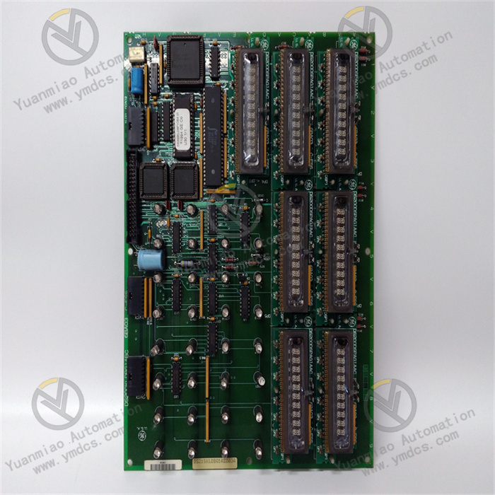
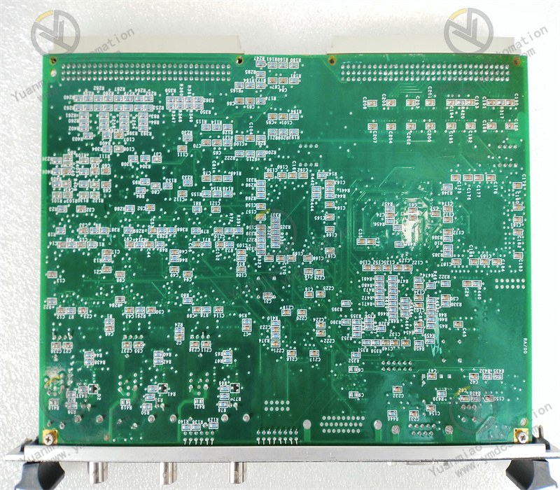
IS215VCMIH2CB adopts dedicated VME‑controller hardware architecture for GE Mark V IS200/IS215 series. Its core components include high‑performance main processor, large‑capacity program‑and‑data memory, VME‑bus interface chip, redundant‑data‑synchronization circuit, power‑management unit, multi‑group status LEDs and debugging communication ports. Internal hardware implements high‑low‑voltage partition and multi‑power‑domain isolation. CPU core, memory, VME‑bus interface and communication ports are powered by independent power domains to prevent single‑point power‑supply faults from spreading. VME‑bus interface integrates bus arbitration, data transceiver and address‑decoding circuits to function as Bus Master for scheduling all in‑rack I/O boards.
Gold‑plated pins are adopted on rear‑side VME standard backplane connectors (J1/J2) for reliable mating with rack backplanes. The metal front‑panel hosts LED indicators, debugging serial port and maintenance interface for convenient direct connection with on‑site engineer terminals. The PCB is built with industrial flame‑retardant ruggedized design. All components pass industrial‑temperature‑grade screening and full‑load aging test, optimized for long‑term cabinet‑operation scenarios with continuous running, temperature cycling and electromagnetic interference. As Mark V systems have been in service for over 30 years, OEM spare‑part availability is gradually declining, making high‑quality compatible and refurbished boards vital assets for legacy‑unit maintenance.
4.2 Structural & Engineering Advantages
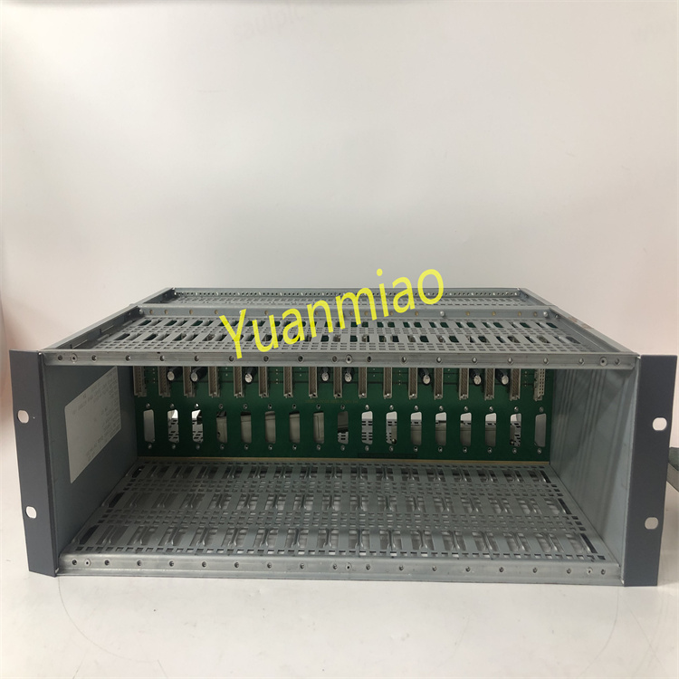
The VME standard 6U modular form factor shares uniform dimensions with other Mark V‑series VME boards. Mixed installation of multiple board types within one control cabinet rack is supported. System expansion only requires inserting corresponding I/O boards into spare rack slots without mechanical‑structure or main‑controller hardware modification. Dual‑redundant controllers are installed in adjacent slots. Redundant‑synchronization signals are routed via dedicated internal backplane traces without extra optical fibers or network cables, delivering compact layout and high reliability.
Unified GE Mark V dedicated engineer‑software suite handles controller configuration, I/O setup, control‑logic programming and fault‑recording analysis. All application programs, parameters and firmware versions can be backed‑up and archived online. Configurations can be restored after board replacement without on‑site reprogramming. Standardized structure and software ecosystem reduce operator‑training overhead and spare‑part varieties. For decades‑old Mark V legacy units, spare‑part management and fault‑replacement capability for core CPU boards such as IS215VCMIH2CB directly determine whether units can safely operate until next major overhaul or retrofitting, rendering them strategic spare‑parts for long‑term plant maintenance.
5. Working Principle
IS215VCMIH2CB VME main controller implements closed‑loop real‑time‑control workflow: VME backplane I/O data acquisition → real‑time control‑logic computation → redundant data synchronization → output and communication distribution → self‑diagnosis and fault tolerance, to fulfill full‑range turbine‑unit control, protection and monitoring functions.
During system operation, acting as VME‑bus Bus Master, the board cyclically scans all in‑rack I/O boards via VME backplane bus to acquire full‑set process signals including field speed, vibration, temperature, pressure, valve position and digital status. After isolation, filtering and A/D conversion by I/O boards, signals are transmitted to main‑controller memory in real‑time over VME bus. Under RTOS scheduling, the main CPU executes turbine‑control application programs at millisecond‑level scan cycles: performing speed PID regulation, load control, fuel‑stroke / IGV‑position closed‑loop control, sequence start‑stop logic and protection‑interlock judgment to generate control output commands.
Control output commands are sent down to DO/DAO channels of corresponding I/O boards over VME bus to drive field actuators (regulating valves, solenoid valves, variable‑frequency drives, etc.). Meanwhile, via serial‑port / Ethernet communication ports, the board uploads real‑time process data, status information, event sequences and trend curves to operator HMI, plant DCS and SIS protection system, and receives remote operation commands, set‑point modifications and parameter downloads to form complete closed‑loop control and monitoring architecture.
Under redundant configuration, primary and standby controllers synchronize all process data, intermediate variables, I/O status and communication information through dedicated high‑speed redundant links to ensure fully consistent operating status. Upon primary‑controller failure, the standby controller automatically takes over control within milliseconds with bumpless output transition. Full‑range self‑diagnosis circuits monitor health status of CPU, memory, power supply, VME bus and communication links. Alarms are triggered via front‑panel LEDs and HMI upon anomalies. Maintenance personnel can hot‑swap the faulty controller online. After system recovery, data synchronization is automatically completed and redundancy is re‑established.
6. Troubleshooting
6.1 Front‑panel Fault LED illuminated or controller offline
| Probable Cause | Inspection Method | Remedial Action |
|---|---|---|
| CPU hardware failure, memory check‑sum error or board self‑diagnosis failure | Check front‑panel LED status; read diagnostic words and fault codes via Mark V engineer terminal | Hot‑swap with spare IS215VCMIH2CB unit per procedure; restore programs and parameters |
| Poor VME‑backplane‑connector contact, pin oxidation or bent pins | Extract the board and inspect J1/J2 connector pins and backplane receptacles | Clean gold fingers and pins; re‑insert and secure the board; repair backplane for bent pins |
| Abnormal VME rack power‑supply output or faulty power‑supply board | Measure backplane +5 V DC voltage against nominal specification; inspect power‑supply‑board LEDs | Troubleshoot rack power‑supply loop; replace faulty power‑supply board; board recovers automatically |
| Damaged or lost EPROM/Flash program after power‑down | Review board power‑on self‑test information and program CRC value | Re‑flash / download valid firmware and application programs; keep system in safe state during downloading |
6.2 Abnormal redundant‑controller switch‑over or primary‑standby desynchronization
| Probable Cause | Inspection Method | Remedial Action |
|---|---|---|
| Mismatched firmware or application‑program versions between primary and standby controllers | Read and compare firmware versions and program CRC values of primary and standby controllers | Unify firmware and program versions; upgrade channels sequentially following OEM manual |
| Redundant‑synchronization‑link failure or abnormal backplane synchronization signals | Review redundancy‑status LEDs and redundancy‑diagnosis information in engineer software | Inspect backplane synchronization connectors; re‑insert controller boards; replace backplane if necessary |
| Long‑term excessive controller load or occasional self‑diagnosis anomaly | Check CPU utilization, scan cycle and event log | Optimize application‑program structure; upgrade controller if required; schedule planned maintenance |
6.3 HMI or DCS communication interruption, frozen data refresh
| Probable Cause | Inspection Method | Remedial Action |
|---|---|---|
| Faulty communication board, loose serial‑port cable or Ethernet cable | Inspect communication‑board LEDs and link connections | Retighten cables; hot‑swap faulty communication board per procedure |
| Incorrect or conflicting IP / serial‑port configuration | Verify board communication‑configuration parameters against HMI/DCS point list | Reconfigure network parameters via engineer software; resolve IP conflicts |
| VME‑backplane communication error or board communication‑port anomaly | Check VME‑bus error counter and communication‑status word | Improve rack grounding and shielding; clean backplane connectors; replace board if required |
6.4 Frozen field I/O data or non‑functional outputs
| Probable Cause | Inspection Method | Remedial Action |
|---|---|---|
| Faulty corresponding I/O board | Locate faulty I/O board via engineer software; inspect board LEDs | Hot‑swap faulty I/O board per procedure; main‑controller board itself is fault‑free |
| VME‑backplane‑bus communication error or slot‑identification failure | Check VME‑bus error counter and slot‑diagnosis information | Improve rack grounding and shielding; clean backplane connectors; re‑insert I/O boards |
| Application‑logic error or forced / interlocked outputs | Monitor logic blocks and output‑variable status online | Remove incorrect forcing; correct logic configuration; re‑download program following MOC procedure |