Description
1. Product Overview
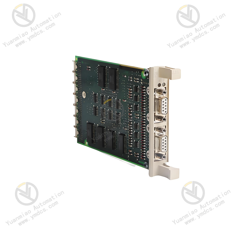
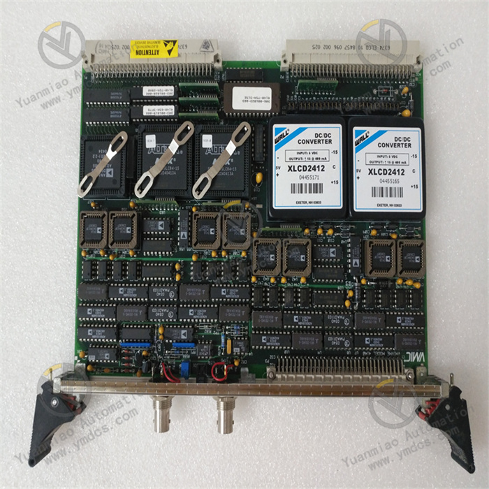
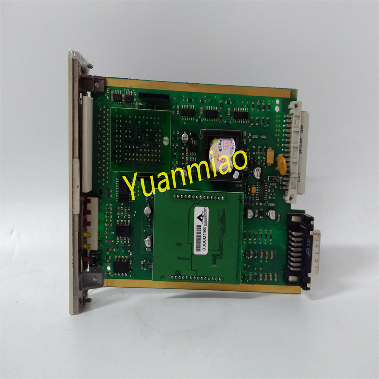
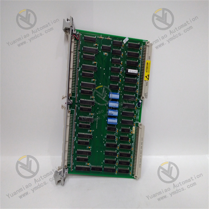
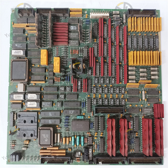
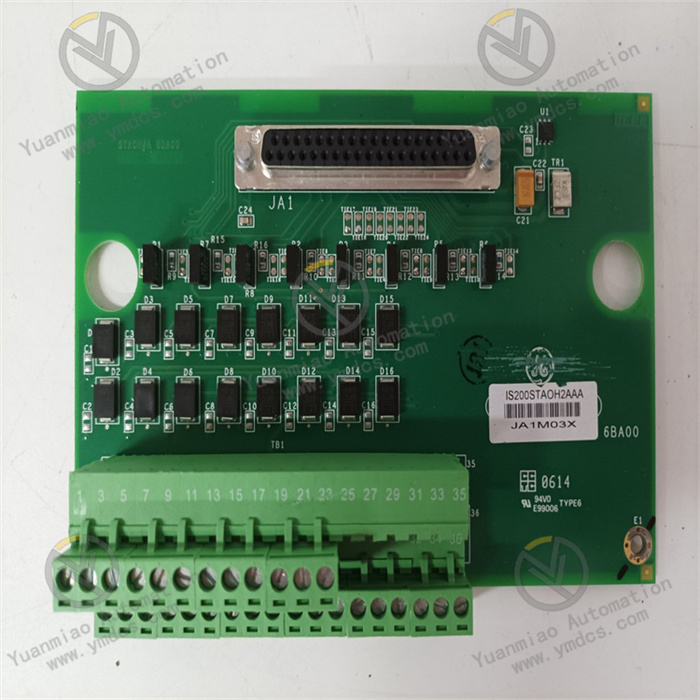
GE IS200STAIH2ABB is an Analog Input Terminal Board of the IS200 series under GE Speedtronic Mark VI turbine control system. It serves as the front‑end hardware for field signal acquisition of Mark VI gas‑turbine and steam‑turbine control systems. Designed for TCS (Turbine Control System), TSI (Turbine Supervisory Instrumentation) and generator control systems of GE gas turbines, steam turbines, hydro‑turbine units and centrifugal compressor units, this board undertakes wiring access, signal isolation, filtering conditioning, long‑lead compensation and terminal transfer functions for field 4‑20 mA DC current signals, thermocouple millivolt‑level voltage signals, RTD resistance temperature detector signals, and process analog signals such as pressure, liquid level and valve position feedback. It safely and steadily introduces various field analog measurement points into the main control board of the control system.
It has passed comprehensive industrial‑grade tests including full‑load power‑on aging, temperature cycling, vibration‑shock test, dielectric withstand and electromagnetic interference test. Capable of 7×24‑hour full‑load continuous operation all year round, it endures harsh cabinet conditions in power plants such as high enclosed temperature, dust‑humidity environment, alternating temperature cycles, strong electromagnetic interference and grid voltage fluctuation. Given the long remaining service life of Mark VI‑based installed units worldwide, IS200STAIH2ABB, as the core terminal board for analog‑signal acquisition loops, its spare‑part supply, fault replacement and system maintenance are critical for safe operation of legacy on‑site units, and constitute one of the key hardware assets for GE turbine‑control‑system retrofitting and spare‑part stocking.
2. Functional Features
2.1 Centralized multi‑channel analog‑signal access with standardized loop organization
As a dedicated analog‑input terminal board for Mark VI systems, IS200STAIH2ABB integrates multiple standardized screw‑type wiring terminals for centralized access to field 4‑20 mA DC current signals, thermocouple millivolt signals, RTD signals, pressure‑transmitter outputs, liquid‑level signals, valve‑position feedback and other process analog signals. It unifies and classifies scattered field measurement points. Layout strictly follows GE Mark VI original point definition with clear signal zoning, strong‑weak electric separation and distinct wiring marking. It effectively resolves common issues including messy analog‑loop wiring, confused measurement points and cross‑loop interference, making field cabling, loop verification and troubleshooting more standardized and efficient. It perfectly matches standardized turn‑key construction and operation‑maintenance management for gas‑turbine and steam‑turbine control systems.
2.2 High‑precision analog‑signal conditioning with long‑lead compensation against drift
Built‑in dedicated analog‑signal conditioning and long‑lead compensation circuits provide hardware‑optimized constant‑current / constant‑voltage excitation, lead‑resistance compensation, cold‑junction compensation and compatibility for 3‑wire / 4‑wire connection modes for 4‑20 mA current‑loop signals, thermocouple millivolt signals and RTD signals. It effectively counteracts lead‑resistance errors, contact‑resistance drift and thermoelectric‑potential interference introduced by long‑distance field cabling. It guarantees authenticity and accuracy of key measurement‑point data such as casing temperature, exhaust temperature, bearing temperature, lube‑oil temperature, steam pressure and vibration displacement. Measurement deviations and interlock mis‑operations caused by poor terminal contact, inconsistent lead resistance and field thermoelectric potential are avoided, greatly improving monitoring accuracy and operational stability of turbine units.
2.3 Physical strong‑weak electric isolation with hardware‑level loop protection
Physical partitioning and independent‑loop layout separate field weak‑current analog‑signal loops from backplane / power‑supply circuits. Built‑in overcurrent, surge and ESD electrostatic‑protection mechanisms resist transient line surges, electromagnetic radiation and variable‑frequency‑drive harmonic interference. It prevents control hosts and field sensors from damage caused by strong‑electric crosstalk or abnormal power‑supply surges. Single‑loop faults will not propagate to trigger full‑board failure or control‑system anomalies, enhancing anti‑interference performance and fault tolerance of analog‑acquisition loops for complex electromagnetic environments at gas‑turbine sites.
2.4 Native Mark VI compatibility for plug‑and‑play performance
Natively adapted to the backplane architecture of GE Mark VI Speedtronic control systems. Point definitions, signal protocols, mechanical dimensions and connector definitions fully comply with OEM design. No extra adaptor modules, secondary signal conditioning or complex calibration are required. Direct in‑situ installation is supported for both new‑build and legacy Mark VI units. It seamlessly interfaces with peer CPU main‑control boards, system master units, upper‑level HMI and plant DCS to realize real‑time analog‑data uploading, trend storage, over‑limit alarming and interlock linkage. It fits multiple scenarios including new‑unit turn‑key delivery, legacy‑system retrofitting and loop reformation.
2.5 Reliable gold‑plated terminal structure for stable long‑term contact
Industrial‑grade gold‑plated anti‑corrosion wiring terminals feature anti‑oxidation, anti‑corrosion, anti‑loosening and repeated‑mating resistance. They withstand high‑humidity, dusty, oily and vibrating gas‑turbine site conditions, eliminating hidden risks such as signal interruption and parameter jumping induced by terminal oxidation, poor contact or loose connections. Firm terminal locking maintains constant contact resistance with no signal drift, loop open‑circuit or contact bounce during long‑term operation. It greatly reduces risks of protection mis‑action, unit load reduction and unplanned shutdown caused by analog‑loop faults, and extends service life of signal‑acquisition loops.
2.6 Modular debug‑free design for efficient maintenance and replacement
Standardized modular plug‑in structure for Mark VI systems delivers precise rack alignment, easy assembly and secure latching, matching layout of GE standard control cabinets. Clear definitions for standardized terminal interfaces and signal loops require no specialized debugging, system‑logic reconfiguration or control‑logic modification. Non‑destructive in‑situ replacement of faulty legacy analog‑input terminal boards is supported without unit shutdown or large‑scale rewiring. Signal‑acquisition‑loop reformation and hardware upgrading can be completed rapidly, lowering O&M costs, repair difficulty and unit shutdown losses for power‑plant turbine systems.
3. Technical Specifications
3.1 Core Compatibility Parameters
| Item | Specification |
|---|---|
| Complete Part Number | IS200STAIH2ABB |
| Brand | General Electric (GE) |
| Product Series | GE Mark VI / Speedtronic IS200‑series turbine‑control system |
| Product Type | Analog Input Terminal Board |
| Applicable Systems | GE Mark VI gas‑turbine / steam‑turbine TCS, TSI, plant DCS/SIS |
| Matching Hardware | Mark VI VME rack, CPU main‑control board, I/O control pack, power‑supply module |
| Compatible Sensors | 4‑20 mA transmitters, thermocouples, Pt100/Cu100 RTDs, pressure / liquid‑level / valve‑position sensors |
| Core Functions | Centralized multi‑channel analog‑signal access, signal isolation & filtering, long‑lead compensation, terminal transfer, loop surge protection, data uploading |
| Typical Applications | Acquisition of process variables including gas‑turbine exhaust temperature, bearing temperature, steam pressure, lube‑oil pressure, valve‑position feedback and liquid level |
3.2 Electrical Performance Parameters
| Item | Specification |
|---|---|
| Signal Types | Compatible with 4‑20 mA DC current signals, thermocouple millivolt voltage signals and RTD resistance‑temperature‑detector signals |
| Excitation Mode | On‑board constant‑current‑source excitation for high‑precision RTD measurement |
| Channel Isolation | Galvanic isolation between field signals and backplane / power‑supply circuits; physical strong‑weak‑electric partitioning |
| Protection Capability | Built‑in overcurrent, surge and ESD protection to withstand transient abnormal‑voltage line surges |
| Signal Accuracy | Lead‑resistance compensation and filtering conditioning; negligible signal drift for long‑distance transmission |
| Interface Configuration | Industrial screw‑type gold‑plated anti‑corrosion terminals; mating backplane connectors for Mark VI I/O control cards |
| Electrical Stability | 7×24‑hour continuous operation; no loop open‑circuit, signal jumping or terminal‑contact anomalies |
| Insulation Performance | High‑voltage dielectric‑withstand compliance; effective isolation against field strong‑electric interference and leakage risks |
3.3 Environmental & Physical Parameters
| Item | Specification |
|---|---|
| Operating Temperature | Industrial wide‑range design for enclosed power‑plant cabinet conditions |
| Storage Temperature | Suitable for extreme temperature during storage and transportation |
| Operating Humidity | 5 %‑95 %RH (non‑condensing); tolerant to dusty‑humid cabinet environments |
| Environmental Resistance | Dust‑proof, moisture‑resistant, oil‑pollution resistant, temperature‑cycle aging resistant, continuous‑vibration resistant, high‑EMI immunity |
| Installation | Mark VI standard rack plug‑in installation; precise alignment and easy assembly |
| Mechanical Construction | Industrial flame‑retardant ruggedized PCB, insulated protective housing; anti‑loosening, vibration‑resistant, aging‑resistant, flame‑retardant and moisture‑proof |
4. Hardware Configuration & Structural Advantages
4.1 Core Hardware Configuration
IS200STAIH2ABB adopts dedicated analog‑input‑terminal‑board hardware architecture for GE Mark VI IS200 series. Core components include multi‑channel analog‑signal wiring terminals, constant‑current excitation conditioning circuits, signal‑filtering and long‑lead‑compensation units, strong‑weak‑electric isolation modules, surge‑overcurrent‑protection loops, backplane connectors and stabilized‑power‑supply adaptation units. Fine‑partitioned internal‑circuit design completely separates field analog‑input loops, backplane communication loops and auxiliary power‑supply loops to prevent signal crosstalk and distortion at hardware level. Core components and wiring terminals pass strict OEM screening including full‑load aging, thermal shock, vibration fatigue, high‑voltage insulation and electromagnetic‑interference tests. Optimized for long‑term uninterrupted turbine‑unit operation, complex field cabling and harsh cabinet conditions, it reliably implements full‑process functions of field multi‑channel analog‑signal access, isolation, conditioning and transfer.
Gold‑plated contacts are adopted on rear‑side Mark VI standard backplane connectors for reliable mating with peer CPU main‑control boards. Front‑panel screw‑type field‑wiring terminal blocks feature signal definitions fully consistent with OEM drawings for convenient on‑site construction and maintenance. The PCB is built with industrial flame‑retardant ruggedized design. Multi‑point mechanical locking for internal circuits resists hardware poor‑contact, terminal loosening, board deformation and aging under sustained cabinet vibration, temperature cycling, oil pollution and dust.
4.2 Structural & Engineering Advantages
Compact standardized modular structure for GE Mark VI series perfectly fits dense‑installation layout of turbine‑control cabinets with high space utilization, secure mounting and strong adaptability. Industrial flame‑retardant, moisture‑proof and vibration‑resistant rugged materials plus multi‑point locking for internal circuits and terminal bases sustain long‑term cabinet vibration, temperature cycling, humidity and dust. Clearly marked and partitioned board terminals greatly reduce on‑site wiring errors and loop‑troubleshooting difficulty.
Non‑destructive in‑situ replacement of faulty legacy analog‑input terminal boards is supported without cabinet‑rack modification, main‑control‑logic reconfiguration or unit shutdown, lowering retrofitting, O&M and repair costs for turbine systems. Standardized dimensions, terminal layout and installation modes are fully consistent with other IS200‑series I/O terminal boards (digital, speed, vibration etc.). Unified spare‑parts management, on‑site training and fault‑repair workflows for maintenance personnel fully satisfy requirements for long‑term stable operation of signal‑acquisition loops for large‑power‑plant gas‑turbine and steam‑turbine units.
5. Working Principle
IS200STAIH2ABB analog‑input terminal board implements closed‑loop signal‑acquisition workflow: field analog‑signal access → partitioned isolation & filtering → constant‑current excitation & long‑lead compensation → signal conditioning → stable backplane transmission → full‑range hardware protection, to realize regularization, accurate transmission and safe isolation of field analog signals for Mark VI turbine‑control systems.
During operation, field analog signals including 4‑20 mA transmitter signals, thermocouple millivolt signals, RTD signals, pressure / liquid‑level / valve‑position feedback signals are connected to corresponding partitioned terminal loops on the board. All incoming signals first pass partitioned‑isolation circuits for galvanic isolation between field‑sensor loops and control‑system backplane / power‑supply circuits, eliminating strong‑electric crosstalk, power‑supply interference and ground loops. Subsequently, constant‑current‑excitation and filtering‑compensation units supply stable constant‑current excitation for RTDs while counteracting lead‑resistance errors, contact‑resistance drift and thermoelectric‑potential interference induced by long‑distance field cabling, and output stable purified analog signals.
Conditioned analog signals are stably transmitted to peer CPU main‑control boards via rear‑side Mark VI backplane connectors. Main‑control boards perform A/D conversion, linearization calculation and engineering‑quantity scaling. Processed data enter the Mark VI main‑control system for parameter display, over‑limit alarming, trend logging and interlock‑protection logic. On‑board full‑range hardware‑protection circuits real‑time monitor current‑voltage conditions of each partitioned loop. In case of line short‑circuit, overcurrent, surge shock or abnormal leakage, faulty loops are automatically isolated to suppress interference propagation and protect main‑control equipment and field sensors.
Standardized terminal integration and loop optimization resolve pain points of messy analog‑measurement‑point wiring, signal instability and frequent‑loop faults at turbine sites, ensuring accurate monitoring data, reliable interlock protection and controllable unit operation for Mark VI turbine‑control systems.
6. Troubleshooting
6.1 Analog‑measurement‑point display jitter, bouncing or inconsistent with actual values
| Probable Cause | Inspection Method | Remedial Action |
|---|---|---|
| Loose, oxidized or poorly‑contacted field‑sensor terminal wiring | Locate bouncing channels via HMI measurement‑point trends; inspect field terminal crimping status | Disable relevant protections before tightening terminals; clean or replace oxidized terminals; re‑crimp cable lugs |
| Mismatched 4‑20 mA loop load resistance or abnormal power supply | Measure transmitter terminal voltage and loop current | Inspect 24 V DC power supply; adjust load resistance to standard range |
| Aging or characteristic drift of field‑sensor body | Simulate 4‑20 mA signal with standard signal source and compare HMI readings | Replace with same‑model transmitter and recalibrate |
| Strong on‑site electromagnetic interference or non‑standard shield‑grounding | Check cable‑shield grounding modes; separate routing for power cables and signal cables | Single‑point standard grounding for shield layers; separate laying for signal cables and power cables; add filters |
6.2 Measurement‑point bad‑point indication, open‑circuit or over‑limit alarm
| Probable Cause | Inspection Method | Remedial Action |
|---|---|---|
| Damaged field sensor or broken lead‑wire | Verify sensor signal at field terminal box | Replace faulty transmitter; repair broken cables |
| Blown internal‑loop fuse or breakdown of protection components on corresponding terminal‑board channel | Short‑circuit analog signal at terminal‑board input end and check whether bad‑point alarm persists on HMI | Replace channel‑specific protection components or full IS200STAIH2ABB terminal board |
| Poor backplane‑connector contact or main‑control‑board fault | Cross‑reference adjacent channels; inspect backplane‑connector tightness | Re‑plug and clean backplane connectors; troubleshoot peer CPU main‑control board |
6.3 Global abnormal analog data or communication interruption
| Probable Cause | Inspection Method | Remedial Action |
|---|---|---|
| Loose, oxidized or bent‑pin backplane connector | Extract full terminal board and inspect gold fingers and backplane pins | Clean gold fingers and pins; re‑insert and secure the board; repair backplane for bent pins |
| Faulty peer CPU main‑control board | Check main‑control‑board LED status and system alarm messages | Hot‑swap corresponding CPU main‑control board per procedure; terminal board itself requires no modification |
| Abnormal cabinet power supply or faulty power‑supply module | Measure backplane supply voltage against nominal specification | Troubleshoot cabinet power‑supply loops; replace faulty power‑supply module |
6.4 Systematic measurement deviation (globally high / low readings)
| Probable Cause | Inspection Method | Remedial Action |
|---|---|---|
| Wrong sensor range or thermocouple graduation number | Compare configured measurement‑point range / graduation number in system configuration with physical field sensor | Modify range / graduation‑number configuration via Mark VI engineer station and download parameters |
| Loop‑resistance imbalance caused by inconsistent wire gauge | Measure balance of field‑loop conductor resistance | Replace with same‑cross‑section shielded cables to guarantee consistent loop resistance |
| Signal‑conditioning drift induced by board aging | Input standard values with signal source and compare HMI reading deviation | Replace full IS200STAIH2ABB terminal board when deviation exceeds allowable threshold |