Description
Ⅰ. Product Overview
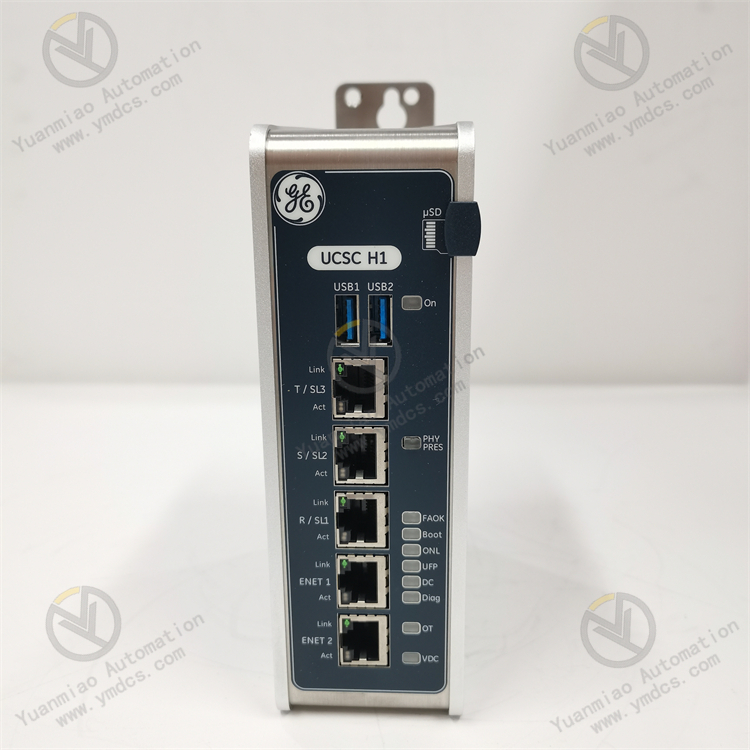
GE IS420UCSCH2A‑E‑V0.1‑A is a universal controller module of the IS420 series under GE Mark VIe (Speedtronic Series) gas / steam turbine control system. It serves as the core computing and scheduling unit of the Mark VIe control system, undertaking central‑processing tasks including turbine control logic computation, I/O data management, redundant communication scheduling, system self‑diagnosis and backplane bus control. Designed for GE gas turbine & steam turbine TCS (Turbine Control System), TSI (Turbine Supervisory Instrumentation), interconnection with Bently Nevada 3500 system and power‑plant auxiliary control systems, it acts as the “main controller” hardware responsible for unit‑wide coordination, algorithm computation and redundancy management within Mark VIe.
Within the complete order number IS420UCSCH2A‑E‑V0.1‑A: IS420 denotes the hardware code for the new‑generation IS‑series controller of Mark VIe; UCS stands for Universal Controller System; CH2 represents the specific controller model with integrated multi‑channel I/O and communication capability; A indicates hardware revision; E denotes derivative configuration (redundant / simplex / dedicated interfaces); V0.1 is firmware version; the trailing A stands for release revision. The module is natively compatible with Mark VIe V1.0 system rack backplane, and seamlessly integrates with IS220 / IS420 series terminal boards, I/O control packs, power supply modules, switches and gateway modules. It supports simplex or 1oo2 dual‑redundant operation. As the core CPU hardware for digital control systems of gas & steam turbines in modern power plants.
It has passed a full set of industrial‑grade tests including full‑load burn‑in, temperature cycling, vibration‑shock test, dielectric withstand, electromagnetic interference test and long‑term redundant switching test. Capable of 7×24‑hour non‑stop full‑load operation all year round, it withstands harsh cabinet conditions such as high enclosed temperature, dust‑humidity alternation and strong electromagnetic interference as well as grid voltage fluctuation. It solves pain points of traditional turbine controllers such as insufficient computing power, communication lag, single‑point failure, performance degradation over long‑term operation and obsolete spare‑parts. It is key hardware for new‑build combined‑cycle gas‑turbine power‑plant Mark VIe system integration, legacy Mark V/VI retrofitting and strategic spare‑part stocking for critical units, ensuring accurate control logic, reliable redundant switchover and safe turbine operation.
Ⅱ. Functional Features
2.1 High‑Performance 32‑Bit Real‑Time Computation for Full Turbine Control Algorithms
Equipped with high‑performance 32‑bit industrial microprocessor and large‑capacity memory, IS420UCSCH2A runs GE dedicated real‑time operating system (RTOS) and executes complete gas‑ / steam‑turbine control algorithms: speed control, load control, closed‑loop pressure & temperature regulation, sequence start‑stop logic, fuel & inlet‑guide‑vane control, protection interlock and auxiliary‑system interoperation. Configurable millisecond‑level scan cycle meets requirements for fast turbine regulation and emergency protection response. Compared with legacy Mark V systems, computing capacity is multiplied, supporting sophisticated coordinated control, advanced algorithms and multi‑unit group control.
2.2 Native Dual‑Redundancy Architecture with Bumpless Switchover
Supports 1oo2D redundant controller configuration. Active and standby controllers synchronize runtime data, I/O status, program variables and communication status via high‑speed redundant links. Upon active‑controller failure, the standby unit takes over within milliseconds with bumpless transfer; no output jump occurs to field actuators. Faulty controller can be hot‑swapped online without unit shutdown. Redundant links implement CRC check and data consistency monitoring to eliminate control anomalies caused by desynchronization, forming the cornerstone for continuous operation of large gas‑ / steam‑turbine units.
2.3 Multi‑Protocol Industrial Communication for Seamless Integration with Power‑Plant Automation Network
On‑board Ethernet switch ports support Modbus TCP/RTU, OPC, IEC 61850 and Profibus DP. It enables bidirectional real‑time data exchange with unit HMI, SIS protection system, Bently Nevada 3500 monitoring system, plant DCS, SCADA and plant‑level MIS. Redundant Ethernet ring, PRP and HSR seamless redundancy protocols are supported; single port / link fault will not interrupt communication, fulfilling digitalization, networking and remote‑operation requirements of modern smart power plants.
2.4 On‑Board I/O & Flexible Expansion for Diverse Configurations
The module integrates partial general‑purpose DI/DO/AI channels. Via Mark VIe backplane bus, dozens of IS220 / IS420 I/O terminal boards and control packs can be expanded, covering signal types such as speed, vibration, temperature, pressure, valve position and discrete signals. System scale is flexible: compact control station with simplex controller plus limited I/O for small gas turbines; distributed multi‑controller deployment for large combined‑cycle plants partitioned by functions (gas‑turbine control, steam‑turbine control, HRSG and auxiliary control) with unified software configuration.
2.5 System‑Wide Online Self‑Diagnosis for Precise Fault Localization
Multi‑layer self‑diagnosis covers CPU, memory, clock, power supply, backplane bus, redundant links and communication ports. Front‑panel multi‑color LEDs indicate power, run, fault, redundancy and link health. With GE ToolboxST engineering software, operators remotely read diagnostic words, SOE sequences, trend curves and fault snapshots to pinpoint root causes without cabinet disassembly, greatly shortening troubleshooting and repair duration.
2.6 Standardized Modular Design for Efficient Maintenance & Replacement
Adopts Mark VIe standard hot‑swap plug‑in rack‑mount structure with precise positioning and secure locking. Dimension, terminal definition and mounting are unified with other IS420 series modules for high spare‑part compatibility. ToolboxST connects via Ethernet / serial port to accomplish program upload/download, parameter configuration, firmware upgrade and fault‑recording analysis without special tools or complex wiring, improving commissioning, modification and field repair efficiency.
Ⅲ. Technical Specifications
3.1 Core Adaptation Parameters
| Item | Content |
|---|---|
| Complete Order Number | IS420UCSCH2A‑E‑V0.1‑A |
| Brand | General Electric (GE) |
| Product Series | GE Mark VIe / Speedtronic IS420 Turbine Control System |
| Product Type | Universal Controller (UCS) |
| Compatible Systems | GE Mark VIe gas‑ / steam‑turbine TCS, TSI, plant DCS/SIS, Bently Nevada 3500 interconnection |
| Matching Hardware | IS220/IS420 I/O terminal boards, control packs, power modules, switch modules, operator panels |
| Redundancy | 1oo2D dual‑controller redundancy, bumpless active‑standby switchover |
| Core Functions | Real‑time turbine control computation, I/O data management, redundant communication scheduling, system self‑diagnosis, backplane bus control, HMI/DCS data interaction |
| Typical Applications | Combined‑cycle power‑plant gas‑turbine control, industrial steam‑turbine control, gas‑driven compressor units for long‑distance pipelines, HRSG for gas‑turbine plants, industrial drive turbines |
3.2 Electrical Performance Parameters
- Processor: High‑performance 32‑bit industrial RISC microprocessor running GE RTOS
- Memory: Large‑capacity Flash/RAM for application program, parameter, event and trend storage; power‑fail retention supported
- Power Supply: Powered by redundant Mark VIe rack backplane power supply, nominal 24 V DC with wide input tolerance
- Scan Cycle: Configurable at millisecond level for fast turbine regulation & protection response
- Communication Interfaces: Multi‑port Ethernet (copper / fiber optional); Modbus TCP, OPC, IEC 61850, Profibus‑DP supported
- Redundant Link: High‑speed active‑standby synchronization link with CRC check; millisecond‑level bumpless transfer
- On‑Board I/O: Limited integrated DI/DO/AI; massive I/O expansion via backplane for IS220/IS420 modules
- Electrical Stability: 7×24 h full‑load continuous operation without performance degradation, communication stall or redundancy‑switchover failure
3.3 Environmental & Physical Parameters
- Operating Temperature: Industrial wide‑range for enclosed power‑plant cabinet environment
- Storage Temperature: Meets extreme temperature requirements for storage & transportation
- Operating Humidity: 5 %‑95 %RH (non‑condensing); tolerant to dusty high‑humidity cabinet conditions
- Environmental Resistance: Dust‑proof, moisture‑resistant, oil‑resistance, thermal‑cycling aging resistance, vibration endurance and high EMI immunity
- Compliance Standards: IEC industrial safety, EMC and turbine‑control‑system industry specifications
- Mounting: Mark VIe standard rack plug‑in installation; hot‑swap supported
- Front‑Panel Indicators: Multi‑LED for power, run, fault, redundancy status and communication‑link health
- Mechanical Construction: Industrial flame‑retardant reinforced PCB, insulated enclosure, anti‑vibration and anti‑aging
Ⅳ. Hardware Configuration & Structural Advantages
4.1 Core Hardware Configuration
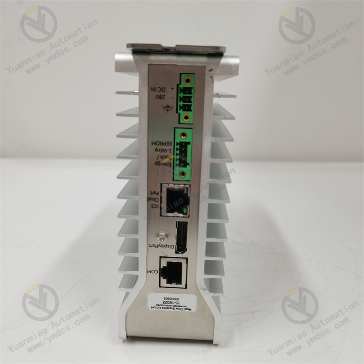
IS420UCSCH2A is built on dedicated Mark VIe IS420 universal‑controller architecture, consisting of high‑performance 32‑bit main processor, large‑capacity program & data memory, multi‑port Ethernet switch chip, backplane bus interface, redundant synchronization link, power‑management unit, status LEDs and maintenance debug port. Internal design implements separation between high‑voltage and low‑voltage circuits with multi‑domain power isolation. CPU core, memory, communication interface and backplane bus are fed by independent power domains to prevent fault propagation from single‑point power failure. Communication chips embed isolated network transformers and ESD protection against field surge and electrostatic discharge.
Gold‑plated backplane edge connectors guarantee reliable rack mating. Front panel integrates LED indicators plus maintenance ports (USB/RJ45) for direct ToolboxST access by field engineers. Flame‑retardant reinforced PCB and components are screened for industrial temperature grade and subjected to full‑load burn‑in, optimized for long‑term cabinet operation under thermal cycling and heavy electromagnetic interference.
4.2 Structural & Engineering Advantages
Adopts compact standardized Mark VIe modular form factor, sharing unified dimension, mounting and terminal layout with IS220 / IS420 I/O terminal boards, control packs and power‑supply modules. Mixed installation within one rack is allowed. System expansion is realized by inserting I/O modules into spare slots without mechanical modification or main‑controller hardware change. Dual‑redundant controllers are mounted in same‑slot or adjacent‑slot arrangement; redundant synchronization signals are routed via dedicated internal backplane traces without extra fiber or copper cabling for compact layout and high reliability.
GE ToolboxST serves as unified engineering platform for controller configuration, I/O setup, logic programming, firmware upgrade, trend monitoring and fault‑recording analysis. Applications, parameters and firmware can be backed‑up online; one‑click configuration restoration is available upon controller replacement without on‑site reprogramming. Standardized hardware‑software ecosystem reduces operator training overhead and spare‑part variety, supporting stable long‑term operation, retrofit and spare‑part stocking of gas‑ / steam‑turbine control systems.
Ⅴ. Working Principle
IS420UCSCH2A implements closed‑loop real‑time control following the workflow: backplane‑bus I/O acquisition → real‑time logic computation → redundant data synchronization → output & communication dispatch → self‑diagnosis & fault tolerance to deliver full turbine control, protection and monitoring.
During runtime, the controller cyclically scans all attached IS220 / IS420 I/O boards over Mark VIe backplane bus to acquire process signals including speed, vibration, temperature, pressure, valve position and discrete status. After isolation filtering and AD conversion on I/O boards, sampled data is transferred into main memory. Under RTOS scheduling, main CPU executes turbine‑control application program within millisecond scan cycles to complete speed PID regulation, load control, fuel / guide‑vane closed‑loop positioning, sequence start‑stop and protection interlock calculation and generate output commands.
Control commands are dispatched via backplane bus to DO/DAO channels of corresponding I/O boards to drive field actuators such as regulating valves, solenoids and variable‑frequency drives. Meanwhile, real‑time process data, status, SOE events and trends are uploaded via Ethernet to operator HMI, plant DCS and SIS. Remote commands, set‑point modification and parameter download are received to form complete closed‑loop monitoring & control.
Under redundant configuration, active and standby controllers synchronize all process data, intermediate variables, I/O states and communication information over dedicated high‑speed links to maintain identical runtime status. Upon active‑unit failure, standby controller performs bumpless takeover within milliseconds. Continuous self‑diagnosis monitors CPU, memory, power supply, backplane bus and communication links. Alarms are triggered via front‑panel LEDs and HMI upon anomaly. Faulty unit can be hot‑swapped online; after recovery, automatic data resynchronization restores full redundancy.
Ⅵ. Common Troubleshooting
6.1 Front‑Panel Fault LED Illuminated or Controller Offline
| Probable Cause | Inspection Method | Remedial Action |
|---|---|---|
| Hardware fault, memory checksum error or CPU self‑diagnostic failure | Read LED status; retrieve diagnostic words & fault codes via ToolboxST | Hot‑swap with spare IS420UCSCH2A per procedure; restore program and parameters |
| Poor backplane‑connector contact, gold‑finger oxidation or pin damage | Inspect gold fingers and backplane pins after module extraction | Clean gold fingers and pins; re‑seat and lock module; repair backplane for damaged pins |
| Rack power‑supply abnormality or power‑module failure | Measure backplane supply voltage; inspect power‑module LEDs | Troubleshoot cabinet power circuit; replace faulty power module for automatic recovery |
| Abnormal firmware or failed program download | Compare firmware version and program CRC in ToolboxST | Download correct firmware and application; maintain safe state during download |
6.2 Abnormal Redundant Switchover or Active‑Standby Desynchronization
| Probable Cause | Inspection Method | Remedial Action |
|---|---|---|
| Mismatched firmware or application between active & standby unit | Read and compare firmware & CRC for both controllers in ToolboxST | Unify firmware and program version; upgrade channels sequentially per OEM manual |
| Redundant‑sync‑link failure or abnormal backplane synchronization signal | Check redundancy LED and ToolboxST redundancy diagnostics | Inspect backplane sync connector; re‑seat controllers; replace backplane if necessary |
| Persistent high CPU load or intermittent self‑diagnostic anomaly | Monitor CPU utilization, scan cycle and event log in ToolboxST | Optimize application structure; upgrade firmware; arrange scheduled maintenance |
6.3 HMI / DCS Communication Loss, Stale Data
| Probable Cause | Inspection Method | Remedial Action |
|---|---|---|
| Loose copper/fiber link, switch‑port fault | Check port Link LED; ping controller IP from HMI | Re‑terminate cable / replace fiber; inspect and reset corresponding switch port |
| IP conflict, incorrect subnet mask or improper VLAN setup | Verify controller IP and DCS/SIS point‑list configuration | Re‑configure network parameters via ToolboxST; resolve IP conflict |
| Communication‑service crash or port anomaly | Check communication status word and error counter in ToolboxST | Restart communication service per procedure; replace controller if required |
| Time‑synchronization fault leading to disordered SOE timestamp | Check NTP/SNTP sync status | Inspect master clock and time‑sync network; restore time‑sync configuration |
6.4 Stale I/O Data or Non‑Responsive Field Output
| Probable Cause | Inspection Method | Remedial Action |
|---|---|---|
| Faulty I/O terminal board or control pack | Locate faulty I/O module via ToolboxST; inspect module LEDs | Hot‑swap defective I/O module per procedure (controller itself remains healthy) |
| Backplane‑bus communication error or slot‑recognition failure | Review slot diagnostics and backplane‑error counter in ToolboxST | Improve rack grounding & shielding; clean connectors; re‑seat I/O modules |
| Application‑logic error or forced / blocked outputs | Monitor logic blocks and output variables online in ToolboxST | Remove incorrect force flags; correct configuration; re‑download under MOC workflow |