Description
1. Product Overview
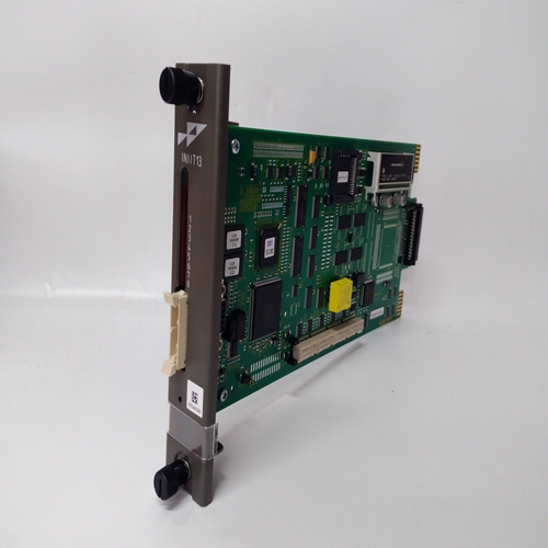
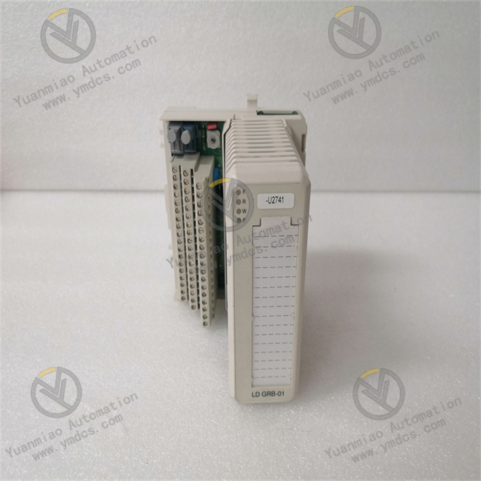
VIBRO‑METER 200‑530‑025‑014 CMC‑16 is a 16‑channel machine condition monitoring module under the Condition Monitoring series of Switzerland‑based VIBRO‑METER (now part of Baker Hughes Bently Nevada). It serves as the core data acquisition and processing unit for the Vibro‑Meter MCM/VM series online condition monitoring and protection system. Designed for large‑scale rotating machinery including steam turbines, gas turbines, hydro‑turbines, centrifugal compressors, axial flow fans, industrial pump units, coal mills and wind turbine gearboxes, the module performs online monitoring of process variables such as vibration, rotational speed, shaft displacement, differential expansion, eccentricity, key‑phase and bearing temperature. Its key functions cover sensor signal access for 16 channels, synchronous sampling, spectrum analysis, envelope demodulation, alarm judgment and system communication.
In the full part number 200‑530‑025‑014, 200 is the prefix for Vibro‑Meter modular chassis/rack series; 530 corresponds to the main hardware model of CMC‑16; 025 denotes configuration options (channel density, interface, power supply); 014 indicates the release revision. The CMC‑16 natively fits the Vibro‑Meter VM600/MCM rack chassis, and seamlessly integrates with series‑matched power supply cards, CPU cards, communication cards, I/O expansion cards and sensor preamplifiers (such as CV‑111, VC‑110 eddy‑current preamplifiers, velocity / acceleration sensors). It supports building distributed online condition‑monitoring networks ranging from single‑unit setups to plant‑wide machinery fleets.
It has passed a full suite of industrial‑grade tests including full‑load signal aging, extreme temperature cycling, vibration‑shock resistance, electromagnetic interference immunity, dielectric withstand and long‑term operational stability. Capable of 7×24‑hour non‑stop full‑load operation, it withstands harsh industrial conditions such as high enclosed cabinet temperature, dust and humidity, alternating temperature cycles, continuous equipment vibration, strong on‑site electromagnetic interference and minor grid fluctuations. Widely deployed in thermal power, hydropower, nuclear power, petrochemical, long‑distance oil‑gas transmission, metallurgy, building materials and wind‑power industries, it implements online condition monitoring, early‑fault warning, protection interlock and predictive maintenance for critical rotating machinery. It acts as core hardware for system integration, retrofitting of legacy monitoring systems and strategic spare‑part stock for key units.
2. Functional Features
2.1 High‑density 16‑channel synchronous acquisition for multi‑measurement‑point coverage
The CMC‑16 integrates 16 independent signal‑acquisition channels, natively compatible with eddy‑current displacement probes (API/PR series preamplifiers), seismic velocity sensors, acceleration sensors, key‑phase sensors, magnetic pickup speed sensors and RTD temperature sensors. A single module can cover all vibration, displacement, speed and key‑phase measurement points of a medium‑sized turbomachine, greatly reducing rack space occupation and cabling costs compared with conventional single‑channel or 4‑channel modules. Channels operate independently without mutual interference. Each channel supports separate configuration, range setup and alarm‑logic programming to adapt flexibly to monitoring requirements of different units and measuring points.
2.2 High‑performance spectrum analysis and envelope demodulation for early‑fault detection
Embedded high‑speed DSP co‑processor enables per‑channel synchronous execution of advanced analytical functions: FFT spectrum analysis, time‑domain waveform capture, amplitude envelope demodulation, order‑tracking analysis, orbit plot, Bode plot and polar plot. It accurately identifies incipient fault signatures such as rotor unbalance, shaft bending, misalignment, oil‑film whirl/whip, inner‑/outer‑race and rolling‑element bearing defects, gear meshing faults, mechanical looseness and surge. Compared with traditional systems limited to overall amplitude monitoring, it enables fault degradation prediction weeks or months in advance, providing sufficient lead‑time for maintenance scheduling and spare‑part preparation.
2.3 Multi‑level programmable alarming and interlock protection for unit safety
Each channel supports user‑configurable three‑level threshold setup: warning, high‑alarm and trip interlock. Alarms can be triggered by multi‑criteria including overall amplitude, harmonic components, envelope amplitude and temperature excursion. Logic functions such as delay, filtering, confirmation delay and alarm blocking are available. The module compares measured data against preset thresholds in real‑time and outputs standard relay alarm / interlock signals upon threshold violation to trigger unit load reduction, audible‑visual alerts or emergency shutdown. Millisecond‑level alarm response prevents major equipment accidents caused by monitoring lag or misjudgment such as component wear, shaft‑system damage and rotor‑stator rubbing.
2.4 Native VM600 rack integration for distributed fleet‑wide scaling
The module natively supports the VM600 rack backplane bus and works plug‑and‑play with series power‑supply cards, CPU cards (e.g. MCM), communication cards (CRC, CVM) and I/O expansion cards. Multiple CMC‑16 modules can be installed in one rack; measured data is aggregated by multi‑channel CPU for system‑level management. Multiple racks can form plant‑wide distributed monitoring networks via Ethernet or serial buses, scaling up to hundreds of measurement channels. Seamless data interfacing is available for Bently Nevada System 1, GE System 1, Emerson AMS, Siemens PI as well as plant‑level SIS / MIS platforms.
2.5 Industrial‑grade noise immunity and wide‑range stable operation
Adopting reinforced industrial electrical architecture and multi‑layer electromagnetic shielding, the module delivers superior EMC performance against interference from frequency converters, coupled noise from power cables, unit radiation and grid fluctuation. With a wide operating temperature range, it maintains stable performance under harsh cabinet conditions: high temperature, humidity, dust, temperature cycling and continuous vibration. No measurement drift, precision degradation or channel failure occurs during long‑term continuous operation to ensure year‑round availability of monitoring systems.
2.6 Modular plug‑in design for efficient field maintenance
Standardized plug‑in architecture for VM600 series enables accurate rack mating, easy assembly and secure latching. Hot‑swap replacement is supported without unit shutdown, power‑off, rewiring or modification of configuration parameters. Uniform mechanical dimensions and interface definitions allow non‑intrusive in‑situ replacement of legacy faulty CMC modules. Maintenance, troubleshooting and retrofit costs are significantly reduced, fitting scenarios including on‑line maintenance, system expansion and hardware upgrade.
3. Technical Specifications
3.1 Core Compatibility Parameters
| Item | Specification |
|---|---|
| Full Part Number | 200‑530‑025‑014 |
| Model | CMC‑16 (Condition Monitoring Controller 16‑channel) |
| Brand | VIBRO‑METER (Switzerland, now Baker Hughes Bently Nevada) |
| Product Series | Vibro‑Meter VM600 / MCM Online Condition Monitoring System |
| Product Type | 16‑channel Machine Condition Monitoring Acquisition & Analysis Module |
| Compatible Systems | VM600 rack‑mount condition‑monitoring system, Bently Nevada System 1, Plant DCS/SIS |
| Supported Sensors | Eddy‑current displacement probes, velocity / acceleration seismic sensors, key‑phase probes, magnetic pickup speed sensors, PT100 RTD sensors |
| Core Functions | 16‑channel synchronous acquisition, FFT spectrum analysis, envelope demodulation, multi‑level alarm evaluation, interlock signal output, backplane bus data upload |
| Typical Applications | Online monitoring and protection for steam turbines, gas compressors, axial fans, industrial pumps, coal mills, hydro‑turbines and wind‑turbine gearboxes |
3.2 Electrical Performance
表格
| Item | Specification |
|---|---|
| Channel Count | 16 independent programmable monitoring channels with electrical isolation between channels |
| Input Signals | Multi‑signal compatibility: eddy‑current displacement, velocity / acceleration vibration, key‑phase, rotational speed and temperature |
| Sampling | 16‑channel synchronous sampling, high‑speed AD conversion, high linearity, low drift |
| Analytical Capabilities | FFT spectrum, time‑domain waveform, envelope demodulation, order‑tracking, orbit plot, Bode plot, polar plot |
| Alarm Output | Multi‑level programmable alarm / interlock relay output, millisecond‑level response |
| Communication Bus | High‑speed VM600 backplane bus; Ethernet, Modbus, OPC accessible via CPU / communication cards |
| Noise Immunity | Multi‑layer electromagnetic shielding, resistant to industrial power‑frequency and high‑frequency interference |
| Electrical Stability | 7×24‑hour full‑load continuous operation without parameter degradation, channel failure or measurement drift |
3.3 Environmental & Physical Parameters
| Item | Specification |
|---|---|
| Operating Temperature | Industrial wide‑range for enclosed cabinets in power & petrochemical plants |
| Storage Temperature | Meets extreme ambient conditions for storage and transportation |
| Humidity | 5 %‑95 % RH, non‑condensing; suitable for dusty and humid cabinet environments |
| Environmental Resistance | Dust‑proof, moisture‑resistant, oil‑resistant, anti‑aging under temperature cycles, anti‑vibration, high EMI immunity |
| Compliance | ISO 10816 / ISO 7919 mechanical vibration monitoring, IEC 61508 functional safety, IEC 61326 EMC |
| Installation | Slot‑mount plug‑in for VM600 standard rack; hot‑swap supported |
| Construction | Industrial flame‑retardant reinforced PCB, metal shielding housing, anti‑loosening, vibration‑resistant and anti‑aging |
4. Hardware Configuration & Structural Advantages
4.1 Core Hardware Configuration
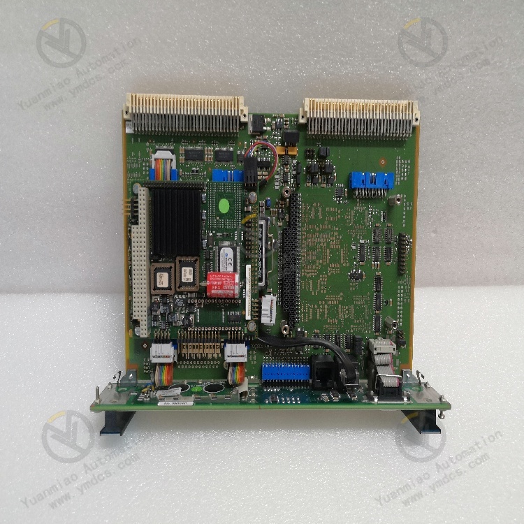
The CMC‑16 adopts dedicated hardware architecture for the Vibro‑Meter VM600 series. Main components include 16 independent signal‑conditioning and AD acquisition circuits, high‑speed DSP spectrum‑analysis co‑processor, multi‑stage digital filters, programmable alarm‑logic unit, backplane bus interface, hardware self‑diagnostic circuit and stabilized power‑supply unit. Internal layout implements channel‑partition isolation and separation of strong / weak current circuits to eliminate crosstalk, power‑supply interference and signal coupling. The analog front‑end precisely conditions ‑24 V excitation and buffered signals from eddy‑current preamplifiers, mV‑level outputs from velocity sensors and key‑phase pulse signals to match different sensor sensitivities and measuring ranges.
Gold‑plated backplane connector at the module rear enables reliable interconnection with rack‑mount power‑supply cards, CPU cards and communication cards for power delivery, data exchange and alarm‑signal routing. Front‑panel LED indicators display channel power status, channel faults, alarm status and module health for quick on‑site diagnosis. Critical components undergo strict OEM screening including full‑load aging, thermal cycling, vibration fatigue and EMC testing, optimized for long‑term operation of large‑scale machinery under continuous vibration and complex electromagnetic environments.
4.2 Structural & Engineering Advantages
Compact standardized plug‑in form factor optimizes rack layout and cabinet space utilization. The flame‑retardant, moisture‑proof and vibration‑resistant metal‑shield housing features mechanically fastened internal circuits, preventing poor contact and signal anomalies under sustained cabinet vibration, temperature cycling and dust‑humidity conditions. Clear channel partitioning plus dual hardware‑software protection delivers high fault tolerance and reliability.
Hot‑swap capability allows module replacement without power‑down, rewiring or configuration reset, enabling non‑intrusive in‑situ substitution of defective legacy CMC modules and lowering maintenance, repair and retrofit costs. Supported by VM600 Protege, System 1 and other engineering software, users can remotely configure channels, set alarm thresholds, retrieve waveforms / spectrums and perform fault analysis. It constitutes key hardware ensuring long‑term stable operation of condition‑monitoring systems in power plants, petrochemical complexes, long‑distance transmission facilities and nuclear‑power sites.
5. Working Principle
The CMC‑16 implements closed‑loop monitoring and protection following the workflow: multi‑sensor signal input → isolated per‑channel conditioning → high‑speed synchronous AD conversion → DSP spectrum / envelope computation → threshold comparison & alarm evaluation → interlock output + backplane bus data upload → continuous self‑diagnosis.
During operation, 16 independent channels simultaneously acquire shaft vibration / displacement signals from eddy‑current probes, housing vibration from seismic sensors, speed reference pulses from key‑phase probes and bearing‑temperature signals from temperature sensors. After preamplifier buffering, multi‑stage filtering, waveform shaping and linear correction, signals are fed to high‑speed AD converters for digital sampling driven by synchronous clock signals.
Digitized data is processed by the on‑board high‑speed DSP co‑processor. Computations include FFT spectrum analysis, time‑domain waveform capture, envelope demodulation, orbit plotting, harmonic extraction and temperature conversion. Monitoring parameters such as overall amplitude, 1X/2X/0.5X harmonic components and envelope indexes are generated. Real‑time comparison is performed between measured parameters and configured alarm / trip thresholds. Under normal conditions, real‑time measurements, spectrums and trends are uploaded to upper‑level CPU and System 1 via backplane bus. When warning or trip thresholds are exceeded, relay contacts are activated to trigger audible‑visual alarms, load reduction or emergency shutdown.
Parallel self‑diagnostic circuits continuously monitor cable open‑/short‑circuit for each channel, preamplifier health, AD acquisition status, backplane‑bus errors and power‑supply voltage. Upon channel‑level sensor or hardware failure, the faulty channel is isolated with front‑panel LED and host‑system alarm notification. Operators can perform hot‑swap replacement; the new module automatically loads configuration and resumes monitoring without disturbance to unit operation.
6. Troubleshooting
6.1 Front‑panel fault LED activated or no data on specific channels
| Probable Cause | Inspection Method | Remedial Action |
|---|---|---|
| Defective sensor/preamplifier, open‑circuit or short‑circuit cabling | Measure preamplifier gap voltage; inspect coaxial cables and connectors | Replace faulty probe / preamplifier; fasten or replace cable assemblies |
| Channel self‑diagnostic failure or AD sampling error | Read channel diagnostic words and fault codes via VM600 Protege software | Hot‑swap CMC‑16 module; restore configuration |
| Poor backplane‑connector contact, gold‑finger oxidation | Observe whether fault disappears after module re‑insertion | Remove module, clean gold‑fingers and backplane pins; firmly seat and lock the module |
| Abnormal rack power‑supply output | Measure backplane supply voltage against nominal specifications | Diagnose and replace defective power‑supply card; automatic module recovery |
6.2 Jittering / drifting vibration or displacement readings inconsistent with actual conditions
| Probable Cause | Inspection Method | Remedial Action |
|---|---|---|
| Changed probe gap, loose mounting or contaminated mounting surface | Measure probe‑to‑shaft gap voltage; inspect probe installation on‑site | Readjust gap to OEM‑specified value; secure probe mounting |
| Preamplifier sensitivity drift or improper cable‑shield grounding | Compare trends of adjacent channels; check shield‑layer grounding | Replace preamplifier; implement single‑point grounding for cable shields |
| Field electromagnetic interference; signal cables laid together with power cables | Review time‑domain waveforms for high‑frequency noise spurs | Physically separate signal cables from power cables; apply shielding and filtering measures |
| Mismatched channel range or sensitivity configuration | Verify configured probe sensitivity (mV/mil) against physical sensor specification | Correct sensitivity and range settings via engineering software; download updated configuration |
6.3 False alarm or spurious interlock actuation
| Probable Cause | Inspection Method | Remedial Action |
|---|---|---|
| Over‑sensitive alarm thresholds or insufficient delay setting | Review historical trends and alarm logs, compare with actual amplitude values | Re‑tune thresholds and delays in accordance with unit operational experience and ISO 7919 |
| Lost key‑phase signal causing incorrect synchronous sampling | Inspect key‑phase waveform and speed reference signal | Readjust key‑phase probe installation; secure key‑phase cabling |
| False alarms induced by transient electromagnetic pulses | Check for events such as motor start‑stop or frequency‑converter switching at alarm timestamps | Increase alarm delay; optimize field shielding and grounding practice |
| Stuck interlock‑relay contacts or defective output circuit | Measure contact continuity with protection functions inhibited | Replace CMC‑16 module or auxiliary relay‑output card |
6.4 Loss of communication to upper‑level System 1 / DCS, no data upload
| Probable Cause | Inspection Method | Remedial Action |
|---|---|---|
| Faulty communication card (CRC/CVM) or loose Ethernet cables | Check LED indicators and link status of rack‑mount communication card | Re‑crimp Ethernet connectors; hot‑swap communication card following procedures |
| Incorrect or conflicting IP / communication‑parameter settings | Cross‑check rack IP configuration against System 1 communication point list | Reconfigure network parameters in engineering software; resolve IP conflicts |
| Backplane‑bus communication errors or CPU‑card hang‑up | Review MCM CPU‑card LED status and backplane‑bus error counters | Restart CPU‑card following operational procedures; replace CPU‑card if necessary |