Description
1. Product Overview
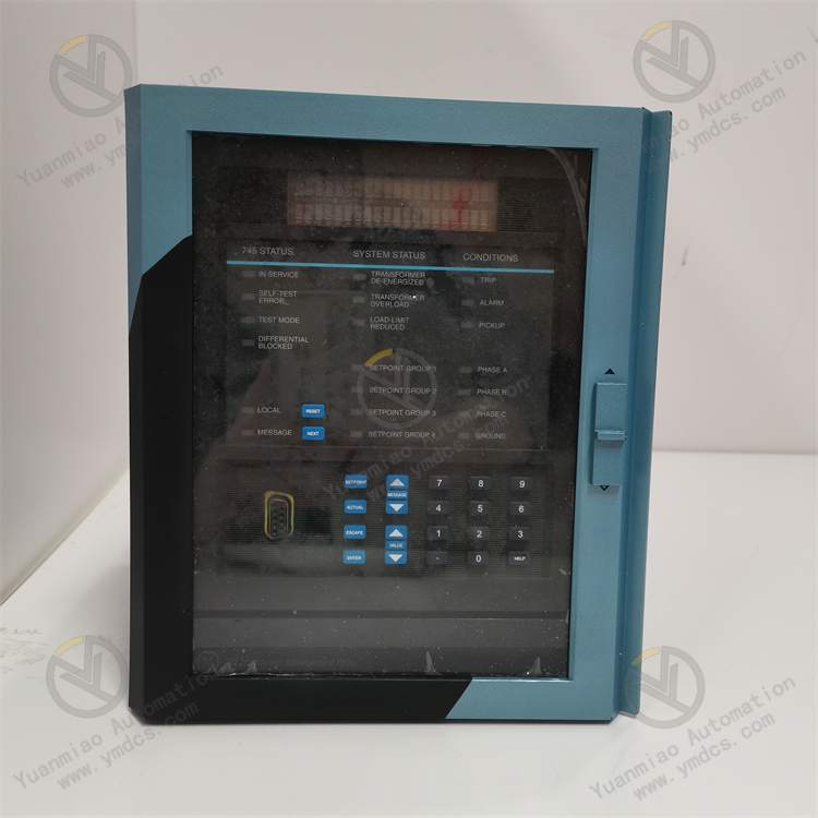
GE 845‑E‑P1‑H1‑G1‑H‑N‑N‑AA‑T‑M‑S‑P‑F‑B‑3E‑T‑W‑B‑4 is a feeder protection relay under GE Multilin series, a new‑generation integrated Intelligent Electronic Device (IED) for protection, measurement and control within the GE UR product family. As the core hardware for complete‑set protection, measurement, control and communication for primary equipment including medium‑/high‑voltage feeders, motors, transformers, capacitor banks and bus couplers, it is widely deployed in substations, industrial main step‑down stations, petrochemical power distribution systems, plant auxiliary power systems for power plants, metallurgical & mining facilities, data centers and rail transit and other critical power supply and distribution scenarios.
Integrating protection, measurement, control, metering, oscillography, Sequence‑of‑Events (SOE) recording and communication functions, the 845 device embeds comprehensive feeder protection elements: three‑phase overcurrent protection, earth/zero‑sequence overcurrent protection, directional overcurrent protection, under‑frequency load shedding, over‑voltage/under‑voltage protection, over‑frequency/under‑frequency protection, reverse‑power protection, auto‑reclosing and post‑trip acceleration. It supports mainstream power communication protocols including IEC 61850 MMS, GOOSE, Modbus TCP/RTU, DNP3 and IEC 60870‑5‑103/104. It can seamlessly interface with Substation Automation System (SAS), plant DCS, enterprise SCADA and smart distribution network master station to realize four‑remote functions (remote measurement, remote signalling, remote control and remote adjustment) as well as uploading of fault oscillography data.
This complete ordering model is configured with high‑range current/voltage inputs, multi‑channel digital input/output, dual Ethernet ports, front‑panel LED indicators and keypad, and flush‑mount hardware options. It complies with IEC 60255 relay protection standards, IEC 61850 communication standards, IEC 60688 measurement standards and national GB/T power industry specifications, with certifications from IEC, CSA and UL. Operating within a wide industrial temperature range of ‑40℃ ~ +70℃ and meeting IEC 60255‑26 vibration and shock resistance requirements, it can withstand harsh operating conditions such as high enclosed cabinet temperature, dust, humidity and heavy electromagnetic interference and grid surges. It serves as core protection‑control hardware for modern smart substations and industrial power distribution systems, and is a key strategic spare part within the GE Multilin product portfolio.
2. Functional Features
2.1 Full‑function Feeder Protection with Comprehensive Protection Logic in Single Device
The 845 device incorporates a complete library of feeder protection elements, including three‑stage definite‑time/inverse‑time phase overcurrent protection (50/51), zero‑sequence/earth overcurrent protection (50N/51N), directional overcurrent protection (67/67N), under‑frequency load shedding (81U/L), over‑/under‑frequency protection, over‑/under‑voltage protection (59/27), reverse‑power protection (32), auto‑reclosing (79), post‑trip acceleration, circuit‑breaker failure protection and CT/PT circuit supervision. All protection element parameters, curves and enable/disable status can be flexibly configured via front‑panel or URPC engineering software. No additional expansion hardware is required to satisfy most protection requirements for medium‑voltage feeders. It replaces multiple traditional electromagnetic and static relays, reducing secondary circuit footprint and maintenance workload in switchgears.
2.2 High‑precision Power Measurement & Metering to Replace Conventional Meters
Equipped with multi‑channel synchronous‑sampling 16‑bit AD converter and high‑precision power metering chip, the device measures real‑time parameters including three‑phase current, three‑phase voltage, frequency, active/reactive power, power factor, energy (Wh/varh), total harmonic distortion (THD), sequence components and unbalance factor. Its measurement performance meets IEC 60688 requirements for Class 0.2 energy meters and Class 0.5 indicating instruments. It can be directly applied as gateway or assessment meters, eliminating separate multi‑function power instruments and lowering secondary‑system investment.
3.3 SOE & Fault Oscillography for Complete Fault Tracing
Built‑in large‑capacity non‑volatile memory stores thousands of time‑stamped Sequence‑of‑Events (SOE) records and multiple latest fault oscillography files. Event resolution is better than 1 ms. Time‑synchronization via IRIG‑B / IEEE 1588 PTP enables precise time alignment with bay‑level protection and control devices across the substation. Fault records are stored in Comtrade format and uploaded to fault‑analysis master station over Ethernet. Waveform playback, impedance calculation and fault‑location analysis can be performed with URPC software, assisting protection engineers to rapidly identify fault type, faulted phase and fault distance so as to shorten power‑outage repair duration.
2.4 Multi‑protocol Communication for Seamless Integration with IEC 61850 Smart Substations
This ordering variant features dual Ethernet ports, natively supporting IEC 61850 MMS reporting, GOOSE trip‑close commands, Modbus TCP, DNP3 TCP/UDP and IEC 60870‑5‑104. Serial interfaces support Modbus RTU, DNP3 serial and IEC 60870‑5‑103. Direct GOOSE interlocking, peer‑to‑peer tripping and SV sampled‑value reception are supported, adapting to multi‑layer automation architectures for smart substations, intelligent distribution networks and plant auxiliary power monitoring. Redundant communication design ensures protection functions and data uploading remain operational upon failure of one single network port or fibre channel.
2.5 Flexible I/O Configuration for Local Primary‑equipment Control & Signal Acquisition
Per ordering configuration, the device includes multiple optically‑isolated digital inputs (DI) and relay‑type digital outputs (DO). DIs acquire circuit‑breaker status, disconnector position, earthing‑switch status, spring‑charging state, remote/local selector and pressure‑abnormal signals. DOs drive circuit‑breaker trip/close circuits, protection outputs, alarm signals, auto‑reclosing blocking and closing interlock circuits. Hardware anti‑chatter is implemented on DI/DO channels, with configurable debounce time and operating delay for compatibility with complex secondary wiring inside switchgears.
2.6 High‑reliability Hardware & Wide‑range Design for Continuous Energized Operation
Industrial‑grade rugged hardware is adopted. Power supply accepts wide‑range AC/DC input (typical 85~265 V AC/DC) with reverse‑connection protection, surge suppression and EMC filtering. The whole unit passes IEC 60255‑26 vibration‑shock test, IEC 60255‑5 dielectric withstand test and Level‑4 immunity under IEC 61000 EMC standards. Front‑panel LED indicators together with LCD and push‑buttons allow on‑site viewing of real‑time measurements, protection settings, event logs and oscillography records. Setting upload/download and firmware upgrade can be performed without device power‑off for convenient maintenance.
3. Technical Specifications
3.1 Core Adaptation Parameters
| Complete Order Number | 845‑E‑P1‑H1‑G1‑H‑N‑N‑AA‑T‑M‑S‑P‑F‑B‑3E‑T‑W‑B‑4 |
|---|---|
| Brand | GE Multilin |
| Series | GE UR Series 845 Feeder Protection Relay |
| Device Type | Digital integrated IED for feeder protection, measurement, control and communication |
| Applicable Primary Equipment | Medium‑/high‑voltage feeders, motors, transformers, capacitor banks, bus coupler switchgears |
| Applicable Systems | Substation Automation System (SAS), power‑plant DCS, enterprise SCADA, distribution‑network master station, IEC 61850 smart‑substation network |
| Core Functions | Multi‑stage overcurrent / earth‑fault / directional protection, auto‑reclosing, under‑frequency load shedding, power measurement & metering, SOE logging, fault oscillography, four‑remote communication, local operation |
| Typical Applications | Industrial main step‑down substations, petrochemical distribution, plant auxiliary power, metallurgy & mining, data centres, rail transit, new‑energy booster stations |
3.2 Electrical Performance Parameters
Auxiliary Power Supply:Wide‑range AC/DC universal power supply, typical 85~265 V AC/DC, with reverse‑polarity protection and surge absorption. Current Input:Multi‑phase CT inputs, rated secondary 5 A or 1 A, wide overload capability, H1 high‑range configuration optional. Voltage Input:Multi‑phase PT inputs, rated 100/110 V; acquisition for phase voltage, line voltage and zero‑sequence voltage. Sampling Accuracy:16‑bit synchronous sampling ADC; current & voltage measurement accuracy class 0.2; energy metering complies with class 0.2S / 0.5S. Protection Response:Millisecond‑level protection response; typical over‑current trip output <30 ms; event time resolution <1 ms. Digital Input (DI):Multi‑channel optically isolated DIs, AC/DC compatible; configurable debounce time. Digital Output (DO):Multi‑channel relay DO outputs; contact rating suitable for trip‑close circuits and signal circuits. Communication Interfaces:Dual Ethernet ports (copper / fiber optional); supports IEC 61850 MMS/GOOSE, Modbus TCP, DNP3, IEC 60870‑5‑104. Serial port supports Modbus RTU, DNP3 serial, IEC 60870‑5‑103. Time Synchronization:IRIG‑B, IEEE 1588 PTP, SNTP, hardware time‑sync contact; event resolution <1 ms.
3.3 Protection & Control Function Configuration
Phase Overcurrent Protection:3‑stage phase overcurrent (50/51); definite‑time & inverse‑time curves with IEC/ANSI standard curve library. Earth‑fault / Zero‑Sequence Protection:Zero‑sequence overcurrent (50N/51N), zero‑sequence overvoltage; compatible with high‑impedance earth‑fault detection. Directional Elements:Directional overcurrent (67/67N); forward/reverse discrimination & directional blocking. Auto‑reclosing:Single/multiple shot auto‑reclose (79); voltage‑check, synchro‑check and non‑synchronous mode. Frequency Protection:Under‑frequency load shedding (81U), over‑frequency (81O), df/dt slip blocking. Voltage Protection:Overvoltage (59), undervoltage (27), PT fuse failure supervision. Additional Protections:Reverse‑power (32), post‑trip acceleration, breaker failure, CT fuse failure supervision, control‑circuit break alarm. Control Functions:Local / remote trip‑close, setting group switching, setting value zone switching, fault recorder trigger.
3.4 Environmental & Physical Parameters
Operating Temperature:‑40 ℃ ~ +70 ℃ wide industrial range; suitable for enclosed high‑temperature cubicles and cold outdoor northern‑region conditions. Storage Temperature:‑40 ℃ ~ +85 ℃, meets extreme temperature for transport & storage. Operating Humidity:5 %‑95 %RH (non‑condensing), withstand high‑humidity cubicle environments. Vibration & Shock Resistance:Complies with IEC 60255‑26 and GB/T 11287 for power‑system relay seismic requirements. Dielectric Withstand:Complies with IEC 60255‑5; secondary‑circuit power‑frequency withstand & impulse withstand qualified. EMC:IEC 61000 series Level‑4 immunity; suitable for heavy EMI switchyard environments. Mounting:Panel flush‑mount / DIN‑rail mount; standard cut‑out dimension; front‑panel gasket for environmental sealing. HMI:Multi‑color LED indicators + graphic LCD + function keys; Chinese / English menu support.
4. Hardware Configuration & Structural Advantages
4.1 Core Hardware Configuration
The ordering model 845‑E‑P1‑H1‑G1‑H‑N‑N‑AA‑T‑M‑S‑P‑F‑B‑3E‑T‑W‑B‑4 is equipped with high‑range CT input module (H1), PT voltage‑input module (G1), dual‑Ethernet communication board (AA configuration), expanded multi‑channel DI/DO (defined by position‑codes T/M/S/P/F/B), firmware version 3E (full feeder‑protection and IEC 61850 features), and front‑panel HMI unit. It adopts high‑performance 32‑bit industrial MCU plus DSP co‑processor architecture, with parallel processing for protection algorithm and measurement computation, guaranteeing millisecond‑level protection response without sacrificing measurement accuracy or communication throughput.
Analogue input channels incorporate high‑isolation CT/PT transformers providing galvanic separation between secondary circuits and low‑voltage electronics to withstand grid surges and CT saturation. DI/DO channels implement dual‑stage isolation combining opto‑couplers and output relays. Relay contact ratings enable direct driving of circuit‑breaker trip‑close coils. Communication board integrates independent CPU and isolated network transformers. Dual ports support ring‑network redundancy and PRP/HSR seamless redundancy subject to protocol configuration. Flame‑retardant PCB and components screened for industrial temperature grade with full‑load burn‑in testing are adopted throughout hardware.
4.2 Structural & Engineering Merits
The 845 follows modular mechanical design of UR series with separable front‑panel and rear‑terminal assemblies. Front‑panel houses LCD, keypad, LED and main CPU board; rear terminals accommodate CT/PT wiring, DI/DO, power‑supply and communication connections. Front‑panel can be hot‑swapped without power‑down and without disconnecting secondary wiring during maintenance, shortening repair time, while rear‑wiring remains fixed to avoid accidental disturbance of live circuits. Standard cutout dimensions support retrofitting of legacy electromagnetic relays and deployment in new‑build smart substations.
URPC (UR PC Tools) engineering software communicates with device via Ethernet or serial port for setting upload/download, logic configuration, event‑waveform retrieval and firmware upgrade. Multiple setting groups are supported for remote switching according to operational modes (summer/winter, high/low load). Uniform mechanical dimensions, terminal definition and software tooling across UR family (750/760 transformer relays, 469 motor protection relays etc.) reduce operator training overhead and spare‑part variety.
5. Working Principle
The GE 845 feeder protection relay implements closed‑loop measurement‑control workflow: CT/PT analogue acquisition → synchronous AD conversion → parallel protection & measurement computation → logic evaluation & output actuation → SOE & oscillography recording → communication uploading & remote control.
During normal operation, primary‑system current from CT and voltage from PT are fed to analogue input board. After signal conditioning and anti‑aliasing filtering, 16‑bit synchronous AD converts analogue quantities to digital samples. DSP performs FFT/DFT fundamental‑component calculation, sequence‑component decomposition, harmonic analysis and energy metering in parallel. Main CPU executes all enabled protection algorithms including phase overcurrent, earth‑fault overcurrent, directional, under‑frequency and voltage protection, comparing real‑time computed quantities against configured settings every processing cycle.
When operating conditions for any enabled protection element are satisfied, logic and timer functions evaluate conditions and actuate corresponding DO relay contacts to issue circuit‑breaker trip command, trigger auto‑reclosing and start fault oscillography. Corresponding LED status is updated and events / oscillography files are logged to non‑volatile memory. Auto‑reclosing logic issues closing command subject to voltage‑check, synchronism‑check and blocking conditions. Under‑frequency load‑shedding trips loads by stages subject to slip‑rate blocking criteria.
Digital‑input channels acquire circuit‑breaker, disconnector and remote/local selector status. After debounce processing these statuses participate in interlock and control logic. Communication subsystem transmits measured values, status changes, events and oscillography files to bay‑level host or DCS following IEC 61850 MMS / Modbus / DNP3 protocols, meanwhile receiving remote control, remote adjustment and setting‑group switching commands to realise complete four‑remote closed‑loop control. Built‑in self‑diagnostics continuously monitor power supply, CT/PT circuits, CPU and communication links. Alarms are raised and potential misoperation outputs blocked upon internal abnormality.
6. Troubleshooting
6.1 No front‑panel display, power‑supply LED off
| Possible Cause | Inspection Method | Remedial Action |
|---|---|---|
| Auxiliary power missing or DC polarity reversed | Measure terminal voltage at power‑supply terminals, verify within 85~265 V AC/DC | Check UPS/DC panel circuit‑breaker; correct polarity; replace blown fuse with correct rating |
| Loose power‑supply wiring | Tighten terminal screws and measure actual terminal voltage | Re‑terminate cables, replace cable lugs if necessary |
| Internal power‑supply module failure | Normal terminal voltage but device fails to boot | Replace with spare 845 unit or return for factory repair; open protection and trip‑circuit isolating links before replacement |
6.2 Protection mal‑operation or failure to operate
| Possible Cause | Inspection Method | Remedial Action |
|---|---|---|
| Incorrect setting or wrong active setting group | Read active setting group and parameters via front‑panel or URPC | Compare against approved setting sheet; download correct settings and activate correct setting group |
| CT secondary open‑circuit / short‑circuit or reversed polarity | Compare measured current reading with primary load current; perform short‑circuit test on CT terminals | Disable protection before CT circuit maintenance; correct polarity; tighten CT secondary terminals |
| Incorrect enable/disable status of protection links | Verify hard‑wired and software‑based protection enable flags | Enable/disable links per operating procedure; adjust software flags via remote control or front‑panel |
| EMI interference or CT saturation | Analyse waveform distortion in fault oscillography files | Improve earthing and cable shielding; adjust anti‑saturation parameters; deploy higher‑anti‑saturation CT if needed |
6.3 Communication loss, no data received by master station
| Possible Cause | Inspection Method | Remedial Action |
|---|---|---|
| Loose or damaged copper/fibre link | Check port Link LED; test with spare cable | Re‑crimp RJ45 connectors or replace fibre; inspect switch port status |
| Misconfigured IP parameters or IP conflict | Read Ethernet configuration from front‑panel and cross‑check with master‑station table | Reconfigure IP, subnet mask, gateway and protocol parameters using URPC |
| Mismatched IEC 61850 ICD/CID files | Compare CID file version used in bay‑level system with device configuration | Download correct CID file and restart communication service |
| Time‑synchronization fault causing disordered SOE timestamps | Inspect device time‑sync status word | Check IRIG‑B/PTP master clock and wiring; restore time‑synchronization link |
6.4 Circuit‑breaker fails to operate or incorrect position indication
| Possible Cause | Inspection Method | Remedial Action |
|---|---|---|
| Worn DO relay contacts or tripping link disabled | Simulate protection operation and measure voltage across output terminals | Enable tripping link; replace output assembly or whole unit; verify trip‑coil power supply |
| Loose DI wiring or oxidised circuit‑breaker auxiliary contacts | Compare DI status shown on front‑panel with actual field equipment position | Tighten DI terminals; clean or replace circuit‑breaker auxiliary contacts |
| Control‑circuit break or incomplete spring charging | Inspect control‑circuit‑break alarm; verify spring‑charging indicator on circuit‑breaker | Restore blown fuse/circuit‑breaker; complete spring charging prior to switching operation |