Description
1. Product Overview
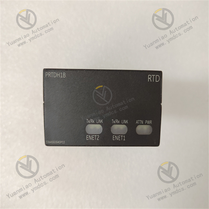
GE IS220PRTDH1B is an RTD thermal‑resistance temperature input terminal board for GE Mark VIe (Speedtronic series) gas‑turbine / steam‑turbine control systems. Belonging to the IS220 series field I/O terminal boards, it works in pair with matching IS220‑series control cards (RTD signal processing control board). It serves as the key front‑end hardware for temperature acquisition loops within the Mark VIe turbine control system.
Designed for GE gas‑turbine and steam‑turbine TCS (Turbine Control System), TSI (Turbine Supervisory Instrumentation), HRSG and auxiliary‑equipment temperature monitoring applications, this board mainly performs wiring termination, signal isolation, long‑lead compensation, filtering conditioning and terminal switching for field Pt100 / Cu100 RTD signals. It safely and reliably brings dozens of field temperature measuring points into the control‑system host.
Adopting the standard Mark VIe terminal‑board architecture, IS220PRTDH1B is fully hardware‑compatible with IS220PRTDH1A and other variants in dimensions, mounting form and signal definitions, and can seamlessly interface with corresponding Mark VIe I/O control packs. It features industrial reinforced PCB, flame‑retardant housing, gold‑plated terminals and shielded‑grounding design. Capable of withstanding long‑term harsh conditions inside turbine‑control cabinets including high temperature, oil contamination, dust, heavy electromagnetic interference and continuous vibration, it is critical hardware for new Mark VIe project execution, legacy Mark V/VI upgrade retrofits, on‑site temperature‑loop troubleshooting and plant strategic spare‑part inventory.
Manufactured in compliance with GE original Speedtronic hardware specifications, IEC industrial safety and EMC standards, the unit undergoes full industrial qualification tests including full‑load burn‑in, thermal cycling, vibration‑shock, dielectric withstand and EMC immunity. It supports 7×24 h non‑stop online operation for power‑generation units, gas‑driven compressors, pipeline gas turbines and industrial steam turbines. It mitigates common field issues such as temperature‑signal drift, long‑wire resistance error, electromagnetic interference, terminal oxidation / loosening and poor contact in acquisition loops, ensuring accurate temperature measurements, reliable interlock protection and safe controllable turbine‑unit operation.
2. Functional Features
2.1 Centralised Multi‑channel RTD Termination for Standardised Loops
As a dedicated Mark VIe RTD terminal board, IS220PRTDH1B integrates multiple standard screw‑type terminals for collective termination of Pt100 / Cu100 RTD inputs, realising unified organisation and zoning of scattered field temperature points. Layout strictly follows GE Mark VIe factory point‑to‑point definitions with clear signal zoning, separation of strong‑weak circuits and legible marking. It eliminates messy wiring, point confusion and cross‑loop interference in traditional temperature circuits, improving efficiency for field cabling, loop verification and fault‑finding, and supporting standardised construction and maintenance for gas‑ / steam‑turbine control systems.
2.2 High‑accuracy RTD Conditioning with Anti‑drift Long‑lead Compensation
On‑board dedicated signal‑conditioning and long‑lead compensation hardware optimises constant‑current excitation for Pt100 / Cu100 RTDs, lead‑wire resistance compensation and compatibility with 3‑wire / 4‑wire configurations. It effectively offsets measurement errors induced by long field cables, contact‑resistance drift and thermoelectric‑potential interference. Readings for casing temperature, exhaust temperature, bearing metal temperature, lube‑oil temperature and steam temperature remain authentic, preventing measurement deviation and inadvertent interlock trips caused by poor terminal contact, mismatched lead resistance or thermal electromotive force, and enhancing overall measurement precision and unit stability.
2.3 Hardware‑level Circuit Protection with Strong‑ / Weak‑current Galvanic Zoning
Physical partitioning separates low‑level temperature‑signal circuits from backplane and power‑supply circuits. Built‑in overcurrent, surge and ESD protection suppress transient line surges, electromagnetic radiation and variable‑frequency‑drive harmonic noise. It prevents damage to controllers and sensors from cross‑coupled high‑voltage disturbances; faults on one channel will not propagate to cause board‑wide failure or system anomalies. Loop immunity and fault‑tolerance are enhanced for harsh electromagnetic environments in turbine halls.
2.4 Native Mark VIe Compatibility for Plug‑and‑play Deployment
Fully aligned with GE Mark VIe Speedtronic backplane architecture in point mapping, signal protocol, mechanical dimensions and connector pin‑out. No intermediate adapters, extra signal conditioning or complex calibration are required. Direct drop‑in replacement is supported for both new‑build and retrofitted Mark VIe installations. Seamless interoperability with companion RTD processing cards, system controllers, HMI and plant DCS enables real‑time temperature uploading, trend logging, alarm annunciation and interlock actuation for new projects, legacy upgrades and loop‑rework scenarios.
2.5 Reliable Gold‑plated Terminals for Stable Long‑term Contact
Industrial gold‑plated corrosion‑resistant screw terminals resist oxidation, corrosion and loosening under repeated cycling. Designed for cabinet environments with high humidity, dust, oil mist and persistent vibration, they minimise risks of signal dropout, temperature jumping and unplanned trips originating from bad terminal contact. Constant contact resistance over service life reduces probability of protection mis‑operation, load run‑back and forced outages caused by temperature‑loop faults and extends service life of measurement circuits.
2.6 Modular Maintenance‑friendly Design for Fast Field Replacement
Standard Mark VIe hot‑swap modular construction enables accurate rack alignment, easy installation and secure latching, conforming to GE cabinet mechanical layouts. Well‑defined terminal assignments and loop definitions eliminate requirement for specialised tuning, logic reconfiguration or control‑system modification. Defective RTD terminal boards can be replaced in‑situ without unit shutdown or extensive rewiring, accelerating loop remediation and hardware upgrades while lowering plant maintenance cost, outage‑repair effort and production loss.
3. Technical Specifications
3.1 Core Application Parameters
| Item | Specification |
|---|---|
| Model | IS220PRTDH1B |
| Brand | General Electric (GE) |
| Series | GE Mark VIe / Speedtronic Turbine‑Control System, IS220 Series |
| Type | RTD Thermal‑resistance Temperature Input Terminal Board |
| Compatible System | GE Mark VIe gas‑ / steam‑turbine control system, TCS / TSI, plant DCS supervisory system |
| Supported Sensors | Pt100, Cu100 industrial RTDs; 3‑wire / 4‑wire connection supported |
| Typical Measuring Points | Casing temperature, exhaust temperature, bearing metal temperature, lube‑oil temperature, steam temperature, auxiliary‑equipment temperature |
| Core Functions | Multi‑channel RTD collective termination, signal isolation & filtering, long‑lead compensation, terminal switching, surge protection, temperature‑data transmission |
| Application Scenarios | Mark VIe new‑build projects, legacy RTD terminal‑board replacement, temperature‑loop fault remediation, gas‑ / steam‑turbine strategic spares |
3.2 Electrical Performance
| Item | Specification |
|---|---|
| Signal Type | Pt100 / Cu100 RTD resistance signal; 3‑wire / 4‑wire compatible |
| Excitation | On‑board matched constant‑current excitation for high‑precision RTD measurement |
| Channel Isolation | Galvanic isolation between field side and backplane / power‑supply circuits; strong‑ / weak‑current zoning |
| Protection | On‑board overcurrent, surge and ESD protection against transient voltage anomalies |
| Signal Performance | Lead‑wire compensation and filtering conditioning; minimal drift over long cable runs |
| Interfaces | Gold‑plated industrial screw terminals; dedicated backplane connector for Mark VIe I/O control‑card interface |
| Electrical Stability | 7×24 h continuous operation; no open‑circuit, temperature jumping or intermittent terminal faults |
| Dielectric Strength | High‑voltage withstand rating mitigating risks of high‑voltage cross‑coupling and leakage |
3.3 Operating Characteristics
| Item | Specification |
|---|---|
| Operation Mode | 7×24 h non‑stop temperature acquisition and signal transmission |
| Response | Real‑time tracking of process temperature with negligible lag |
| Stability | No routine calibration required; measurement accuracy sustained long‑term |
| Application Conditions | Continuous monitoring during turbine start‑up / shutdown, load variation, high exhaust temperature and bearing‑lubrication cycles |
3.4 Environmental & Mechanical Parameters
| Item | Specification |
|---|---|
| Operating Temperature | Wide industrial cabinet temperature range for enclosed turbine‑control cabinets |
| Storage Temperature | Suitable for extreme temperatures during warehousing and transportation |
| Humidity | 5%‑95% RH (non‑condensing); tolerant of dusty high‑humidity cabinet conditions |
| Environmental Robustness | Dust‑proof, moisture‑resistant, oil‑resistant, thermal‑ageing resistant, anti‑vibration, high EMC immunity |
| Compliance | IEC industrial electrical‑safety, EMC and turbine‑control‑system industry standards |
| Mounting | Mark VIe standard rack‑mount plug‑in design; easy alignment and removal |
| Construction | Industrial flame‑retardant reinforced PCB; insulated housing; anti‑loosening, wear‑resistant, ageing‑resistant and moisture‑proof |
4. Hardware Configuration and Structural Advantages
4.1 Core Hardware Configuration
IS220PRTDH1B adopts dedicated IS220‑series temperature‑terminal hardware architecture, integrating multi‑channel RTD terminal blocks, constant‑current excitation‑conditioning circuits, signal‑filtering and long‑lead‑compensation units, galvanic‑isolation modules, surge‑overcurrent protection circuits, backplane connector and power‑supply adaptation unit. Careful circuit zoning physically separates field RTD inputs, backplane communication and auxiliary‑power domains to suppress cross‑talk and signal distortion.
Key components and terminals pass stringent factory screening including full‑load burn‑in, thermal shock, vibration fatigue, high‑voltage dielectric test and EMC immunity. Optimised for continuous turbine‑unit operation, complex field cabling and harsh cabinet environments, the board completes RTD signal termination, isolation, conditioning and transmission.
The rear‑side gold‑plated backplane connector provides reliable mating with companion RTD processing cards. Front‑panel screw‑terminal blocks follow factory drawing pin‑out for convenient installation and troubleshooting. Flame‑retardant reinforced PCB plus mechanically restrained internal circuits resist cabinet vibration, thermal cycling, dust and oil contamination, avoiding intermittent connections, terminal loosening and board‑level ageing‑related degradation.
4.2 Structural and Engineering Merits
Compact modular Mark VIe form‑factor optimises high‑density cabinet layouts with secure installation and good interoperability. Flame‑retardant, moisture‑resistant and vibration‑resistant construction with mechanically locked internal assemblies tolerates sustained vibration, temperature swings and dusty‑humid cabinet environments. Clearly labelled partitioned terminals reduce wiring errors and loop‑diagnosis effort.
Drop‑in in‑situ replacement of faulty legacy RTD terminal boards is achievable without rack modification, control‑logic rework or unit shutdown, lowering retrofit, maintenance and outage‑repair costs. Mechanical dimensions, terminal organisation and mounting style are unified across IS220 I/O families (analogue, digital, speed, vibration etc.), simplifying spare‑parts management, personnel training and on‑site troubleshooting for large‑plant gas‑ and steam‑turbine temperature‑acquisition infrastructure.
5. Working Principle
IS220PRTDH1B implements closed‑loop temperature acquisition workflow: field RTD signal termination → isolated filtering → constant‑current excitation & long‑lead compensation → signal conditioning → backplane transmission → continuous hardware protection, delivering organised, accurately conditioned and safely isolated temperature data to the Mark VIe turbine‑control system.
In operation, Pt100 / Cu100 RTD signals arrive via field shielded cables to corresponding partitioned terminal blocks. Signals pass first through galvanic‑isolation circuits separating sensor wiring from controller backplane and power supplies to reject high‑voltage cross‑coupling, power‑supply interference and ground‑loop effects. Constant‑current excitation together with filtering‑compensation circuits provides stable RTD drive current while cancelling measurement errors from long‑cable resistance, contact‑resistance drift and thermoelectric potentials. Clean conditioned RTD resistance values are forwarded via the rear Mark VIe backplane connector to the companion RTD processing card, which performs AD conversion, linearisation and engineering‑unit scaling. Processed temperature values enter the Mark VIe main controller for display, high/low‑limit alarming, trend recording and interlock‑protection logic execution.
On‑board hardware protection continuously monitors channel‑level current and voltage. Upon short‑circuit, overcurrent, surge or leakage events, affected channels are isolated to contain faults and protect downstream control hardware and field sensors. Through standardised terminal consolidation and loop optimisation, field‑observed pain‑points including messy temperature wiring, signal instability and frequent loop failures are mitigated, securing measurement fidelity, dependable interlocks and safe turbine‑unit operation.
6. Troubleshooting
6.1 Temperature reading jumps, fluctuates or deviates from actual value
| Possible Cause | Inspection Method | Remedial Action |
|---|---|---|
| Loose, oxidised or poorly‑contacted RTD field terminals | Locate erratic channel via HMI trend plots; inspect crimp quality on‑site | Disable associated protections before tightening terminals; clean or replace oxidised terminals; re‑crimp cable lugs |
| Incorrect 3‑wire / 4‑wire wiring; uncompensated lead resistance | Verify field sensor wiring against board terminal‑assignment drawings | Re‑check polarity of A/B/C conductors per GE drawings and correct connections |
| Degraded or drifted field RTD sensor | Inject simulated RTD resistance values with a resistance box and compare HMI readings | Replace with matching Pt100 / Cu100 probe and recalibrate |
| Severe EMI or improper shield grounding | Check cable‑shield termination; segregate signal and power‑cable routing | Implement single‑point shield grounding; physically separate signal and power cables; add filtering components if required |
6.2 Temperature point reports open‑circuit, bad‑point status or out‑of‑range alarm
| Possible Cause | Inspection Method | Remedial Action |
|---|---|---|
| Failed RTD sensor or broken field cable | Measure RTD resistance at field junction box against Pt100 reference tables | Replace defective RTD probe; repair broken cabling |
| Blown channel‑level protection component or damaged on‑board circuit | Inject simulated RTD resistance at board terminals; observe if bad‑point alarm persists | Replace damaged channel‑protection components or complete IS220PRTDH1B terminal board |
| Poor backplane‑connector contact or faulty companion RTD processing card | Cross‑compare adjacent working channels; inspect backplane connector seating | Clean and re‑seat backplane connector; troubleshoot and replace companion RTD processing card |
6.3 Global abnormal temperature readings or loss of communication
| Possible Cause | Inspection Method | Remedial Action |
|---|---|---|
| Loose / oxidised backplane connector or damaged pin contacts | Remove terminal board and inspect gold‑plated fingers and backplane pins | Clean contacts; firmly re‑latch board; repair or replace backplane for damaged pins |
| Faulty companion RTD processing card | Observe card LED status and system alarm logs | Hot‑swap the RTD processing card following site procedures; terminal board itself remains unchanged |
| Cabinet power‑supply anomaly or power‑module failure | Measure backplane supply voltages against nominal ratings | Troubleshoot cabinet power‑supply circuits; replace defective power module |
6.4 Systematic measurement offset (globally high or low readings)
| Possible Cause | Inspection Method | Remedial Action |
|---|---|---|
| Wrong RTD characteristic curve selected (Pt100 / Cu100 mis‑assignment) | Verify configured sensor type in Mark VIe engineering station against physical field sensors | Correct RTD type setting in configuration and download to controller |
| Unbalanced lead resistance from mismatched conductor cross‑sections | Measure DC resistance of each of the three RTD lead wires | Install matched 3‑core shielded cable to ensure equal lead‑wire resistance |
| Drifted on‑board constant‑current excitation due to board ageing | Apply precision reference resistance and quantify HMI reading offset | Replace IS220PRTDH1B terminal board when deviation exceeds allowable tolerance |