Description
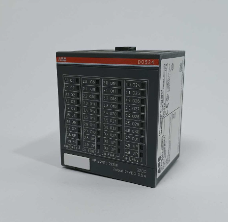
ABB DO524 1SAP240700R0001
I. Overview
ABB DO524 1SAP240700R0001 is a digital output module that belongs to the supporting I/O module system of ABB S500 series programmable logic controllers (PLCs). It converts the digital logic signals output by the PLC master control unit into electrical signals that can directly drive external executive components, achieving precise control and status feedback of various executive devices in industrial sites. It serves as a key hub connecting the PLC control system and on-site executive mechanisms.
II. Product Features
Multi-channel and High-load Driving Capacity: Equipped with 32 independent digital output channels, each channel can provide an output specification of 24VDC and 0.5A, adopting a 1-wire system design. It can drive multiple external executive components (such as relays, solenoid valves, indicator lights, etc.) simultaneously, meeting the application requirements of parallel control of multiple devices.
High-reliability Industrial-grade Architecture: Strictly complying with ABB's design standards for industrial automation products, it selects high-quality industrial-grade components and precision manufacturing processes, and has passed rigorous environmental stress screening and reliability verification. It has excellent anti-electromagnetic interference capability and operational stability, greatly reducing the failure rate under complex industrial working conditions.
Comprehensive Signal Processing and Protection Functions: Integrating core functions such as signal isolation, filtering, and amplification, it can effectively improve the quality of output signals and avoid the impact of on-site interference on control signals. Meanwhile, it is equipped with fault protection mechanisms such as overcurrent and short-circuit protection, which can monitor the status of output channels in real time to prevent the expansion of faults from damaging the module and external equipment.
Convenient Configuration and Operation & Maintenance Experience: Supporting multiple programming languages, it is compatible with the programming habits of different users. The module configuration process is simple and easy to understand, reducing debugging difficulty. Adopting a modular plug-and-play design, it is convenient for installation and disassembly. Combined with clear interface markings and status indicator lights, it is easy for operation and maintenance personnel to intuitively monitor the working status of each channel, quickly locate fault points, and improve operation and maintenance efficiency.
- Good System Compatibility: As a dedicated supporting module for the ABB S500 series, it can be perfectly compatible with the same series of PLC master control units, realizing high-speed data interaction with the CPU through the backplane bus. The standardized installation dimensions and interface design facilitate system integration and expansion, simplifying the construction process of the overall control system.
III. Technical Parameters
1. Core Basic Parameters
- Product Model: DO524 1SAP240700R0001
- Product Series: Supporting I/O Module for ABB S500 Series Programmable Controllers
- Product Type: Industrial-grade Digital Output Module
- Manufacturer: ABB (ASEA Brown Boveri)
- Place of Origin: Sweden
- Product Number: 1SAP240700R0001
- EAN Code: 4013614482717
- Mounting Method: Modular Plug-and-play Installation (compatible with S500 series standard backplanes)
- Core Functions: Digital Signal Conversion, Output Driving, Status Monitoring, Fault Detection and Feedback
- Application Scenarios: Industries such as electric power, elevators, intelligent parking, automobile manufacturing, feed processing, aluminum smelting, refrigeration, steel, and glass; motor control, lighting control, heating control, fan control, pump control, etc.
2. Electrical Performance Parameters
- Working Power Supply: Compatible with industrial standard power supply (refer to the physical manual for details)
- Number of Output Channels: 32-channel digital output (independent channel design, supporting parallel output)
- Output Signal Type: Digital Switch Signal
- Output Voltage: 24VDC
- Output Current: Maximum 0.5A per channel
- Wiring Method: 1-wire System
- Isolation Method: Signal Isolation between Channels (refer to the physical manual for specific parameters)
3. Environmental and Physical Parameters
- Operating Temperature: -25℃ to +70℃ (wide-temperature design, suitable for extreme industrial environments)
- Storage Temperature: -40℃ to +85℃
- Relative Humidity: 5% to 95% (no condensation)
- Protection Class: IP20 (module body, suitable for installation in control cabinets, dust-proof and solid foreign object intrusion prevention)
- Electromagnetic Compatibility: Compliant with industrial-grade electromagnetic compatibility standards, with strong anti-electromagnetic interference capability
- Module Dimensions: Standardized Installation Dimensions (subject to the actual product)
- Weight: Approximately 0.5-0.8kg (subject to the actual product)
IV. Working Principle
The core working principle of the ABB DO524 1SAP240700R0001 digital output module is a closed-loop control process of "Signal Reception - Isolation and Conversion - Power Driving - Status Monitoring - Feedback Transmission". Through the collaborative work of internal functional units, it realizes the safe and accurate conversion and transmission of PLC control signals into driving signals for on-site executive equipment. The specific working process can be divided into five core stages:
The module establishes a communication connection with the ABB S500 series PLC master control unit through the backplane bus, and receives the digital logic control signals (0/1) sent by the master control unit. These signals correspond to control commands such as "stop/start" for external executive equipment. Meanwhile, it receives configuration commands from the master control unit to complete the initialization setting of parameters such as output mode and fault protection threshold.
The received control signals enter the internal optoelectronic isolation unit. The optocoupler realizes electrical isolation between the input control signals and the output driving circuit, effectively avoiding the impact of strong on-site electromagnetic interference and ground potential difference on the PLC master control unit and the module's core circuit. The isolated signals are processed by the shaping and filtering circuit and converted into stable driving control signals, preparing for subsequent power amplification.
The control signals after isolation and conversion enter the power amplification unit. The internal driving chip amplifies the weak signals into electrical signals with sufficient driving capacity (24VDC, 0.5A), which are then transmitted to external executive components (such as relays, solenoid valves, indicator lights, etc.) through 32 independent output channels, driving the executive components to complete corresponding actions (pull-in, disconnection, lighting, etc.).
The module is equipped with a built-in channel status monitoring circuit, which collects the voltage and current signals of each output channel in real time to determine whether there are faults such as overcurrent, short circuit, and open circuit in the output channels. Meanwhile, it monitors key parameters such as the module's own working voltage and internal temperature to ensure the normal operation status of the module.
V. Common Fault Troubleshooting
1. No Output from Channels/External Equipment Fails to Operate
- Disconnect the module power supply, check the wiring between the corresponding channels and external equipment, correct wrong wiring, re-plug and fasten the wiring connectors, replace damaged and aging lines, and ensure reliable connection.
- Test the performance of external executive equipment separately, connect a standard 24VDC power supply to the equipment to verify whether it can operate normally, and replace the equipment with the same model if it is faulty.
- Use a multimeter to measure the working power supply voltage of the module to ensure the voltage is stable within the rated range, and repair the power supply fluctuation or power supply interruption problem.
- After disconnecting the power supply, check the output fuse of the corresponding channel; if the fuse is blown, replace it with a fuse of the same specification and power on again for testing.
- If the above measures are ineffective, the internal power driving circuit of the module is most likely faulty, and it is necessary to contact professional maintenance personnel or ABB official after-sales service for inspection and repair.
2. Abnormal Output from Channels/Misoperation of Executive Equipment
- Replace the output lines with shielded cables, adopt single-end grounding for the shielded layer (grounding resistance ≤4Ω), separate the signal lines from power cables (spacing at least 30cm), and keep away from strong electromagnetic interference sources such as frequency converters and high-power relays.
- Check the wiring of the corresponding channels, re-fasten the connectors, replace aging and damaged lines to ensure no virtual connection in the wiring.
- Check the grounding condition of the module, ensure that the module grounding terminal is reliably grounded, improve the system grounding loop, and reduce ground potential interference.
- Check the output signal of the PLC master control unit; if the output of the master control unit is abnormal, troubleshoot the fault of the master control unit.
- If the above measures are ineffective, the internal isolation circuit of the module may be faulty, and it is necessary to contact professional personnel for inspection, repair or module replacement.
3. Module Fails to Communicate with PLC Master Control Unit
- Disconnect the power supply, check the wiring of the backplane bus between the module and the PLC master control unit, correct wrong wiring, fasten loose connectors, and replace damaged communication lines.
- Check and correct the module address through PLC configuration software or module DIP switches to ensure it is consistent with the address configured in the system and avoid address conflict.
- Use a multimeter to measure the working power supply voltage of the module to ensure the voltage is stable within the rated range and repair the power supply fault.
- Restart the module and the PLC master control unit to re-establish the communication connection.
- If the communication still fails, the internal communication chip of the module may be faulty, and it is necessary to contact ABB official after-sales service for inspection and repair.
4. Module Overheating/Simultaneous Failure of Multiple Channels
- Disconnect the module power supply immediately, check the ambient temperature of the field; if it exceeds 70℃, install cooling fans or improve ventilation conditions in a timely manner, and keep the module at a safe distance of at least 30cm from high-power heat-generating equipment.
- Clean dust and debris on and around the module to ensure unobstructed heat dissipation channels, and do not block the heat dissipation vents of the module.
- Check the external equipment connected to each output channel to confirm that the equipment load does not exceed the rated driving capacity of the channel (0.5A), replace the overloaded equipment or add a driving amplification link.
- Use a multimeter to measure the input power supply voltage to ensure stable output within the rated range and repair the problem of excessively high voltage.
- If the module still overheats frequently after taking the above measures, the internal heat dissipation components or power supply circuit may be faulty, and it is necessary to stop using the module immediately and contact professional maintenance personnel for treatment.