Description
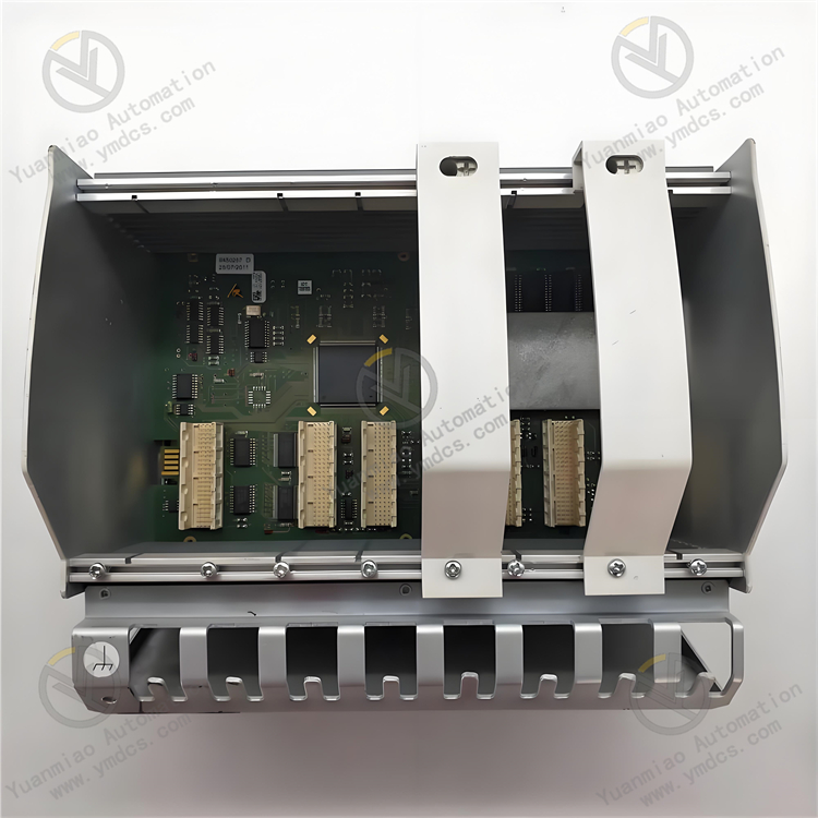
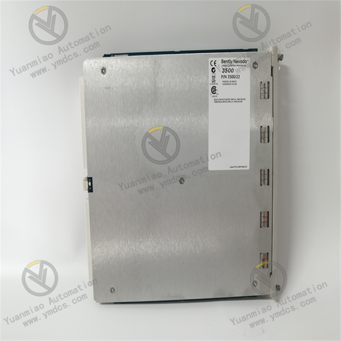
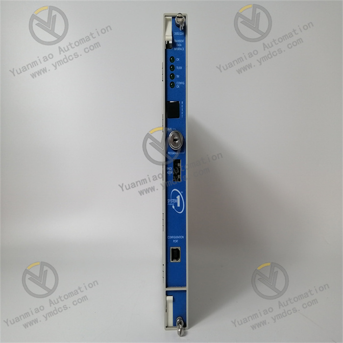
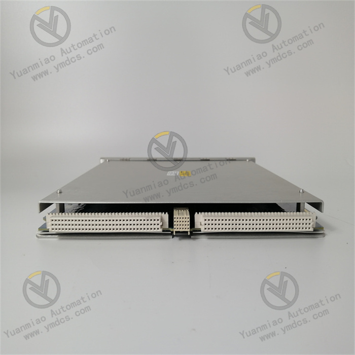
Bently Nevada 3500/22M 288055-01 is a vibration monitoring module with the following functional features:
High-Precision Measurement: Capable of accurately measuring parameters such as vibration velocity, acceleration, and displacement with an accuracy of ±5%. It can detect minute displacement changes, making it suitable for high-precision applications.
Wide Operating Temperature Range: Operates stably in temperatures ranging from -40°C to 80°C (-40°F to 176°F), ensuring reliable performance in harsh industrial environments.
High Protection Rating: With an IP67 rating, it is effectively dustproof and waterproof, adapting to various complex industrial environments.
Multiple Communication Interfaces: Supports RS-485 and Ethernet interfaces, facilitating data transmission and communication with other devices or systems.
Fault Warning and Diagnosis: By collecting and analyzing vibration data, it can identify and diagnose mechanical faults such as bearing wear, unbalance, and looseness, and promptly issue alarms or trigger maintenance actions. It provides real-time monitoring of equipment operating status, fault warnings, and diagnostic information to enhance equipment reliability and production efficiency.
Good Compatibility: Compatible with the Bently 3500 series monitoring system, enabling easy system integration and configuration.
Data Collection and Transmission: As a Transient Data Interface (TDI) module, it can connect to M-series monitors (such as 3500/40M, 3500/42M, etc.), continuously collect steady-state and transient dynamic (waveform) data, and transmit data to host software via Ethernet links for remote monitoring and analysis.
Technical Parameters:
- Dimensions: 145 mm × 154 mm × 40 mm (5.7 in × 6.1 in × 1.6 in).
- Weight: 0.75 kg (1.65 lb).
- Power Supply: 24VDC.
- Operating Temperature Range: -30°C to +65°C.
- Storage Temperature Range: -40°C to +85°C.
- Humidity: 95% non-condensing.
- Ethernet: 100Base-FX fiber (MT-RJ connector), maximum data transfer rate of 100Mbps.
- USB: Type B connector (for local configuration).
- Data Acquisition: Up to 16 channels, with a maximum sampling rate of 256k/s.
- Data Storage: 1GB memory.
- Number of Channels: 22 channels.
- I/O Types: Inputs: analog, digital; Outputs: analog, digital, relay.
- Protection Rating: IP65.
- Velocity Accuracy: ±0.05%.
- Vibration Accuracy: ±1%.
- Data Interfaces: 10Base-T/100Base-TX Ethernet (auto-sensing); 100Base-FX fiber Ethernet.
- Functions: Monitors parameters such as bearing vibration, temperature, and speed; supports spectral analysis, time-domain analysis, trend analysis, and other data analysis functions; provides fault warning and protection.
Working Principle:
- Data Acquisition: The module supports various vibration sensors (e.g., accelerometers, velocity sensors, displacement sensors). It collects transient data (e.g., impacts, vibrations) during equipment operation through these sensors. Using high-precision sensors and advanced signal processing technology, it can acquire signals at extremely high sampling rates to accurately capture rapid changes in equipment operation. It also supports multi-channel simultaneous data acquisition to improve efficiency.
- Data Processing and Transmission: Collected data is preliminarily processed within the module and then transmitted to host computers (e.g., GE's System 1 condition monitoring and diagnostic software) via Ethernet. The module interacts with M-series monitors (e.g., 3500/40M, 3500/42M) in the Bently Nevada 3500 series monitoring system to continuously collect steady-state and transient dynamic (waveform) data, which is transmitted to host software via Ethernet links. Additionally, the module has a USB interface for easy connection to computers for data transmission and analysis.
- Data Analysis and Application: The module provides powerful data analysis functions to help users quickly locate faults. By analyzing collected transient data, it can diagnose equipment failure causes, assess operating status, and predict potential faults, providing critical information for equipment fault diagnosis and condition evaluation to facilitate timely maintenance and improve equipment reliability.
Operation Guide for Bently Nevada 3500/22M 288055-01 Transient Data Interface Module (TDI):
I. Installation and Connection
I. Installation and Connection
- Hardware Installation
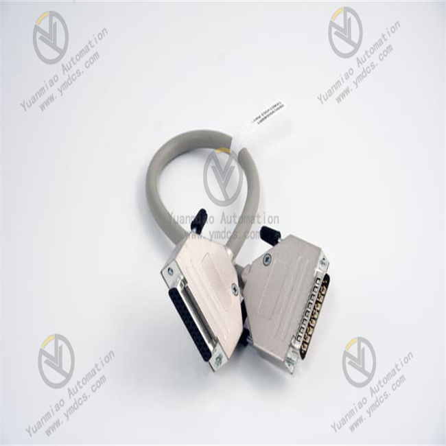
- Connect the module's RJ45 interface to the monitoring network or host computer (e.g., server, engineer station) via an Ethernet cable.
- For local debugging, directly connect to a computer via the USB interface.
- Ensure reliable power and grounding connections for the module and frame to avoid electromagnetic interference.
- Installation Location: The module is suitable for the Bently Nevada 3500 series frame and must be inserted into a specified slot (typically slot 12 or as per system configuration).
- Physical Connections:
- Sensor Connection
- Connect sensor signals to the module's input channels via shielded cables (the number of channels depends on the module configuration).
- Ensure proper grounding of the cable shield to reduce noise interference.
- Supported Sensor Types: Accelerometers, velocity sensors, displacement sensors (e.g., eddy current probes).
- Signal Access:
II. Configuration and Parameter Setting
- Software Tools Preparation
- Bently Nevada 3500 frame configuration software (e.g., 3500/92 configuration tool): Used to configure the module's address and channel parameters in the frame.
- Host analysis software (e.g., GE System 1, Pruftechnik): Used for data collection, storage, and analysis.
- Required Software:
- Basic Module Configuration
- Set the module's IP address, subnet mask, and gateway via software to ensure network connectivity with the host.
- Enable the TCP/IP protocol and configure the data transmission port (refer to the manual for default ports).
- Open the 3500 frame configuration software and identify the module's slot.
- Set the module's logical address (e.g., slot number), number of channels, and sampling parameters (sampling rate, resolution, etc.).
- Configure sensor type, measurement range, and filter parameters (e.g., anti-aliasing filter frequency).
- Frame Configuration:
- Network Configuration:

III. Data Collection and Analysis
- Data Collection Modes
- Initiates transient data collection via hardware triggering (e.g., external digital signals) or software triggering (e.g., vibration amplitude exceeding a threshold).
- Captures waveform data (e.g., time-domain waveforms, spectra) during transient events such as impacts or start/stop processes.
- Continuous Collection: Continuously monitors steady-state vibration data for trend analysis.
- Triggered Collection:
- Data Viewing and Analysis
- Fault Diagnosis: Identifies abnormal equipment frequencies (e.g., unbalance, misalignment, bearing fault characteristic frequencies) through spectral analysis.
- Transient Event Analysis: Compares waveforms in normal and faulty states to locate impact sources or mechanical looseness.
- Trend Prediction: Predicts equipment performance degradation trends through historical data fitting.
- Connect to the module's IP address to establish a data communication link.
- Select collection channels, time windows, and analysis types (e.g., spectral analysis, envelope analysis, waveform playback) in the software interface.
- Real-time display of vibration amplitude, waveforms, and spectra, with support for zooming and marking peak frequencies.
- Host Software Operations:
- Typical Analysis Functions:
IV. Maintenance and Troubleshooting
- Daily Maintenance
- Judge the module's status via LED indicators on the frame front panel:
- Power Indicator (PWR): Steady on indicates normal power supply.
- Communication Indicator (COM): Flashing indicates normal Ethernet communication.
- Fault Indicator (FAULT): Red light indicates module abnormality; check configuration or hardware connections.
- Status Inspection:
- Data Backup: Regularly export configuration files and historical data to external hard drives or servers to prevent data loss.
- Common Fault Troubleshooting
Fault Phenomenon Possible Causes Solutions No data transmission Interrupted network connection, incorrect IP configuration Check network cables, restart the module, reconfigure IP High data noise Unshielded sensor cables, poor grounding Replace with shielded cables, check grounding terminals Failed triggered collection Improper trigger threshold setting, abnormal hardware trigger signal Adjust thresholds, test trigger signal integrity Module fault light on Hardware damage, poor slot contact Reinsert the modu