Description
1. Product Overview
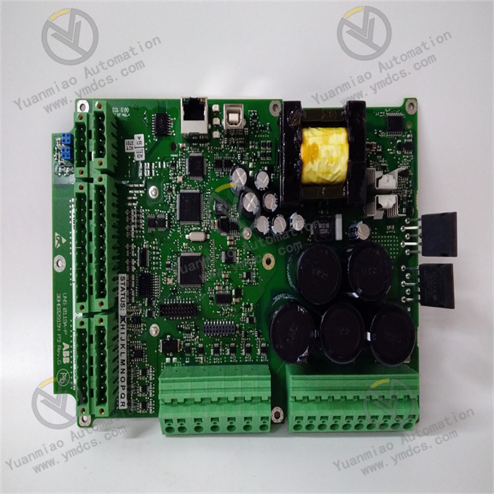
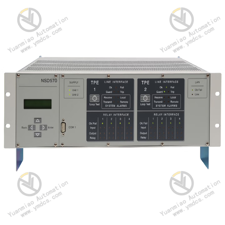
ABB NSD570 is a high‑performance remote protection communication device (pilot protection equipment) for power systems and belongs to the core equipment of ABB power communication‑protection series. Designed for substations, transmission‑line and power‑grid interconnection scenarios, it realizes high‑speed, reliable and secure remote transmission of protection commands, tripping signals and power‑grid status data over multiple communication media. It serves as a key supporting unit for power‑system pilot differential protection, remote tripping and power‑grid stability coordination. Compatible with traditional relay‑protection interfaces and the new‑generation smart‑grid standard IEC 61850, the device enables seamless interconnection between conventional and intelligent substations. Featuring a modular architecture, ultra‑low transmission latency and strong anti‑interference performance, it is widely applied in power‑grid transmission‑distribution networks at all voltage levels, renewable‑energy step‑up substations and industrial captive power plants, and meets the requirements of 24‑hour uninterrupted stable operation of power systems.
2. Core Technical Parameters
2.1 Basic Specifications
- Model: NSD570
- Equipment Type: Power‑system remote pilot‑protection communication device
- Core Function Orientation: Pilot protection for transmission lines, remote‑trip command transmission, cross‑substation coordinated communication of power grids
2.2 Communication and Transmission Parameters
- Transmission Latency: Digital‑link latency < 5 ms, satisfying timing requirements for fast protection operation of high‑voltage transmission lines
- Communication Protocols: Native support for IEC 61850 and GOOSE message interaction; compatible with traditional contact‑interface protocols
- Transmission Media: Adaptable to various industrial communication media including optical fibre, power‑line carrier and dedicated leased‑line networks for flexible networking
- Command Channels: Supports concurrent transmission of independent protection commands over multi‑channels; protection‑logic channels can be configured flexibly
2.3 Electrical and Interface Parameters
- I/O Voltage Range: Wide‑range compatibility with 24 VDC ~ 250 VDC, matching DC power‑supply systems of substation DC panels
- Insulation Performance: High dielectric‑withstand strength, compliant with surge‑immunity standards for power equipment, capable of resisting transient over‑voltage and impulse voltage on power grids
- Interface Configuration: Integrated traditional hard‑wired contact interfaces and Ethernet communication ports, meeting demands for legacy‑equipment renovation and new‑build intelligent‑substation projects
- Human‑Machine Interface: Built‑in web‑based HMI, supporting on‑line configuration, status monitoring and parameter modification via web‑browser access
2.4 Environmental and Structural Parameters
- Operating Temperature: ‑20 ℃ ~ +70 ℃, suitable for full‑range working conditions of power‑distribution rooms, outdoor cabinets and main control rooms of substations
- Protection Class: Industrial‑grade dust‑proof and electromagnetic‑interference‑resistant design, adapting to complex high‑EMC electromagnetic environments inside substations
- Structural Features: Compact modular design with high hardware integration, small cabinet footprint and support for modular upgrade and expansion
3. Product Functions and Core Advantages
3.1 Core Product Functions
- Pilot‑Protection Signal Transmission: Enables bidirectional high‑speed exchange of differential signals, tripping commands and blocking commands between protection relays at both ends of transmission lines, supports pilot differential‑protection functions and realizes accurate fault isolation of transmission‑line faults.
- Compatible Interconnection between Intelligent and Conventional Equipment: Supports both IEC 61850 GOOSE intelligent‑message transmission and traditional hard‑contact signal transfer, removes communication barriers between new and old substations and facilitates intelligent upgrading and renovation of power grids.
- Independent Multi‑channel Command Transmission: Independently‑configured multi‑channels can transmit multiple protection commands such as tripping, alarm, blocking and coordinated control simultaneously without mutual interference, delivering high logic reliability.
- On‑line Monitoring and Self‑diagnosis: Complete built‑in hardware self‑check, link monitoring and fault‑alarm functions. It can detect communication disconnection, link anomalies and module failures in real time and actively upload alarm information for maintenance.
- Flexible Configuration and Upgrade: Web‑based visual configuration without dedicated software tools; modular hardware upgrade supports flexible transition and reconstruction between analogue, digital and Ethernet‑based systems.
3.2 Core Product Advantages
- Ultra‑fast Transmission for Power‑grid Safety: Millisecond‑level ultra‑low latency fully satisfies timing requirements for rapid fault clearance on high‑voltage transmission lines, effectively reduces fault outage duration and improves overall power‑grid stability.
- Full‑scenario Compatibility for New‑and‑old Renovation: Supports both legacy relay‑protection devices and intelligent‑substation equipment, perfectly applicable to existing‑grid renovation, new‑build smart‑substation and cross‑system interconnection projects.
- Industrial‑grade Ultra‑high Reliability: Designed in strict accordance with power‑industry EMC and insulation standards; lightning‑surge‑resistant, impulse‑tolerant and high‑EMI‑immune. Zero code errors, unwanted trips and failure‑to‑trip events during long‑term operation.
- Modular Design for Low Maintenance Costs: Standard modular architecture allows independent replacement of faulty single units instead of whole‑device replacement. On‑line commissioning and testing can be performed without interrupting normal system operation.
- Flexible Networking and Strong Expandability: Compatible with multiple communication media and mainstream power‑system protocols, adaptable to multi‑level power‑grid topologies and supporting future system expansion and logic upgrades.
- User‑friendly Visual Maintenance: Browser‑based HMI requires no installation; link status, message data and fault logs can be accessed at any time for convenient and efficient maintenance.
4. Typical Application Scenarios
- High‑voltage Transmission‑line Protection: Pilot differential protection and remote‑trip signal transmission for transmission lines of 110 kV, 220 kV and above
- Intelligent‑substation Networking: Protection‑signal interconnection, GOOSE message exchange and cross‑substation coordinated control between intelligent and conventional substations
- Renewable‑energy Power Stations: Line‑protection communication and remote interlock‑trip control for grid‑connection breakers at photovoltaic and wind‑power step‑up substations
- Industrial‑Mining Captive Power Plants: Pilot‑protection communication for high‑voltage distribution feeders and grid‑interconnection tie‑lines of enterprise captive power stations
- Smart‑grid Renovation Projects: Upgrading of ageing conventional substations to intelligent substations, expansion of protection‑communication systems and compatibility reconstruction between new and legacy equipment
- Power‑grid Stability‑control System Supporting: Remote command transmission and status interaction for power‑grid stability‑control devices and interlock‑control systems
5. Installation, Operation and Maintenance Guidelines
- The equipment adopts standard rack‑mounted embedded installation. It shall be installed inside relay‑protection cabinets in dry, dust‑free and non‑corrosive‑gas environments. Ensure good cabinet ventilation and heat dissipation to avoid stability degradation caused by excessive accumulated heat.
- Complete power‑supply, signal and communication wiring strictly in accordance with secondary‑circuit specifications for power systems. Match standard substation DC power supplies and prevent over‑voltage, poor contact and mis‑wiring to guarantee stable power feeding.
- Construct communication links in compliance with specifications for respective transmission media. Use shielded cables for optical‑fibre and Ethernet wiring and implement single‑point earthing properly to avoid message loss and transmission anomalies induced by electromagnetic interference.
- Perform equipment self‑check, link test and protection‑logic linkage test before commissioning. Verify signal‑transmission latency and command‑transceiver accuracy to ensure protection‑logic compliance with power‑grid operating requirements.
- Check equipment operating status, link conditions and fault logs regularly via web‑based HMI during routine maintenance, and eliminate hidden risks such as communication attenuation and link anomalies in a timely manner.
- Carry out system expansion and parameter modification under power‑off conditions or after switching the device to off‑line mode. Arbitrary modification of core protection parameters under live‑operation status is forbidden so as to prevent unwanted tripping or failure‑to‑trip of power‑grid protection.
- Replace faulty equipment with original spare parts of the identical model to guarantee full consistency of communication protocols, parameter configurations and logical functions, and ensure overall compatibility and stability of the power‑grid protection system.