Description
1. Overview
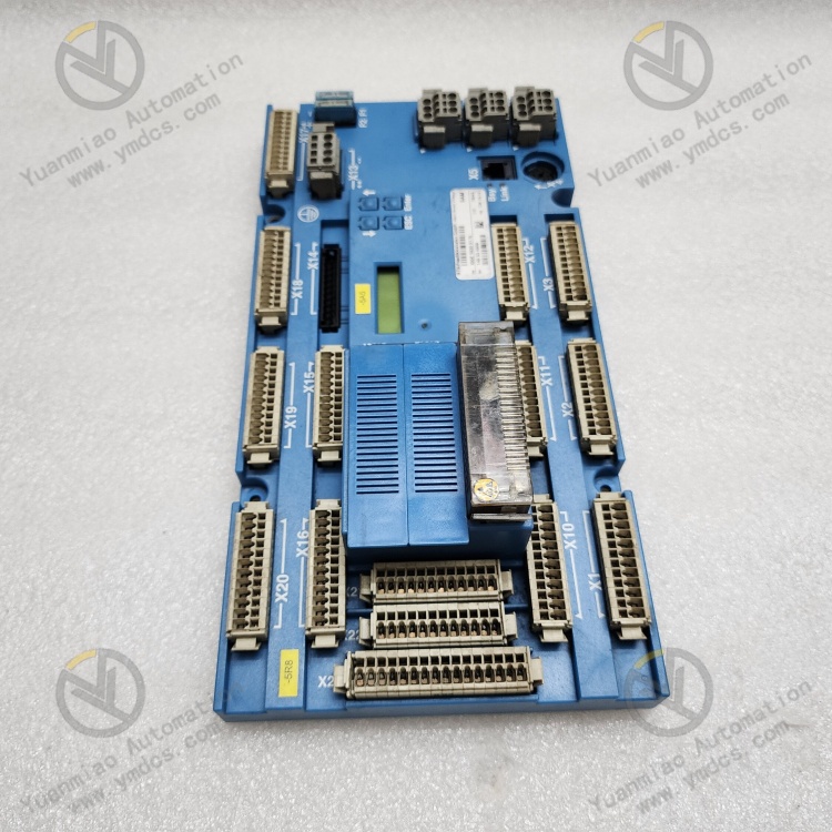
MTU ELEKTRONIK X00E50206616 is an exclusive engine main‑control communication interface module for German MTU electronic control system. It belongs to the electronic‑control supporting system of high‑end MTU diesel/gas generator sets and industrial power units. It acts as the core data‑exchange bridge between MTU engine ECU main‑control unit, upper‑level monitoring system, local control cabinet and remote operation‑maintenance platform.
Designed for high‑power MTU industrial power equipment, this module is widely applied in heavy‑duty continuous‑operation scenarios including marine power, land‑based generator sets, oil‑field power units and industrial‑mining standby power supplies. It undertakes core functions such as unit operating‑data acquisition, protocol conversion, communication forwarding, fault‑data uploading and remote‑parameter interaction.
Integrating multi‑bus compatible communication architecture, hardware‑level signal isolation, data error‑check & correction and surge‑protection circuits, the module fully complies with MTU original electronic‑control design standards and marine‑grade industrial‑protection specifications. It features outstanding communication stability, excellent anti‑interference performance, precise data transmission and zero‑drift during long‑term operation to adapt to harsh working conditions.
It perfectly meets the requirements of intelligent monitoring, remote O&M, fault diagnosis and data traceability for all MTU electronically‑controlled units. As an indispensable standard precision component of MTU power‑unit electronic‑control system, it guarantees 7×24‑hour uninterrupted stable operation of the units.
2. Functions and Features
2.1 Core Functions
Multi‑protocol bus data interaction: Natively adapted to MTU proprietary electronic‑control communication protocol and compatible with standard industrial‑bus communication. It synchronously collects full‑dimensional unit operating parameters including engine speed, oil temperature, coolant temperature, oil pressure, load power, exhaust temperature, start‑stop status and fault codes, and realizes bidirectional data exchange between ECU and upper‑level systems.
Intelligent protocol conversion and data forwarding: Supports mutual conversion between unit proprietary protocol and general industrial protocols. It standardizes and encapsulates raw engine electronic‑control data, and stably forwards data to local‑cabinet display screen, PLC control system, remote monitoring platform and O&M terminal, resolving compatibility issues for multi‑device data interconnection.
Real‑time fault‑data acquisition and uploading: Continuously monitors unit electronic‑control fault signals. It accurately captures various unit hazards such as overspeed, overtemperature, low‑pressure, overload, sensor abnormality and communication failure. Fault time‑series data, fault codes and working‑condition parameters are recorded in real time to provide complete‑data support for fault diagnosis and traceability.
Hardware‑isolated anti‑interference transmission: Built‑in galvanic isolation, signal filtering and surge‑suppression circuits thoroughly suppress strong electromagnetic interference, power‑supply fluctuation and line‑borne noise from power units. It eliminates data packet loss, garbled code and transmission interruption, and ensures stable communication links under complex industrial and marine conditions.
Online parameter interaction and configuration adaptation: Supports remote reading of unit operating parameters, real‑time status refresh and basic‑parameter configuration & calibration. Cooperated with dedicated MTU O&M software, it completes unit‑parameter commissioning, working‑condition optimization and program adaptation to satisfy refined unit‑operation‑management demands.
Link self‑check and fault self‑diagnosis: Equipped with communication‑link self‑check function. It automatically identifies faults such as bus open‑circuit, loose‑wire connection, protocol mismatch, ECU communication interruption and module hardware anomaly, outputs alarm signals actively and pinpoints fault locations to reduce O&M troubleshooting difficulty.
Long‑term stable data caching & storage: Supports temporary‑data caching and time‑series‑data recording. Key unit operating data can be automatically cached during short‑term communication interruption and auto‑retransmitted upon link recovery to avoid loss of unit‑condition data and guarantee data integrity and continuity.
Full‑working‑condition adaptive linked monitoring: Adapts to full operation states including unit start‑stop, no‑load, full‑load, variable‑load and fault shutdown. It synchronizes data between electronic‑control system and monitoring system to achieve blind‑spot‑free monitoring without status lag.
2.2 Product Characteristics
Original‑equipment high‑precision adaptability: OEM module exclusively matching MTU diesel/gas‑unit electronic‑control system with fully‑compatible hardware and software. Secondary debugging is not required; incompatibility, data distortion and communication anomalies caused by protocol mismatch are avoided.
Marine‑grade heavy‑duty protection: Adopts military‑grade components and marine‑protection design. It withstands alternating high‑low temperature, strong vibration, high humidity, dust‑oil pollution and intense electromagnetic interference, suitable for harsh environments such as vessels, field sites and industrial‑mining facilities.
High‑stability low‑failure transmission: Optimized bus‑transmission algorithm with built‑in data error‑correction, retransmission and verification mechanism. Zero‑data‑drift and no‑communication‑stuttering are maintained for long‑term operation with near‑100 % transmission accuracy, satisfying high‑precision‑monitoring requirements of power units.
Modular lightweight design: Compact integrated structure occupies little cabinet space. Easy disassembly‑assembly and neat wiring support standard‑rack mounting for fast old‑to‑new module replacement with strong retrofitting adaptability.
Wide‑temperature reliable long‑cycle operation: Subjected to strict aging, vibration and temperature‑cycling tests with extremely low failure rate. It supports uninterrupted long‑duration unit operation; service‑life matches the service cycle of power equipment.
Visual status monitoring: On‑board dedicated LED indicators directly display module power‑supply, communication‑link, data‑transmission and fault‑alarm status for on‑site quick judgment of module operating‑condition and fault type.
Maintenance‑free long‑term operation: Pure‑circuit integrated design without wearable mechanical parts. Only periodic dust‑removal inspection is required in daily‑service, greatly cutting unit‑O&M cost and workload.
3. Technical Specifications
| Item | Specification |
|---|---|
| Model | X00E50206616 |
| Brand / Manufacturer | MTU ELEKTRONIK (MTU Electronics, Germany) |
| Device Type | Engine Electronic‑Control Communication Interface Module |
| Applicable Equipment | Full range of MTU diesel/gas generator sets, industrial power units, marine power units |
| Core Functions | ECU data acquisition, protocol conversion, bus communication, fault uploading, parameter interaction |
| Communication Architecture | MTU proprietary bus + compatible standard industrial bus |
| Transmission Features | Data verification & error correction, automatic retransmission, offline data cache, real‑time synchronous transmission |
| Protection Design | Galvanic isolation, surge protection, signal filtering, electromagnetic shielding |
| Diagnosis Functions | Link self‑check, communication‑fault diagnosis, hardware‑status self‑test |
| Operating Voltage | Standard industrial DC power supply (compatible with MTU unit electronic‑control system) |
| Operating Temperature | ‑25℃~+70℃, industrial wide‑temperature range |
| Storage Temperature | ‑40℃~+85℃ |
| Ambient Humidity | 5 %‑95 %RH, non‑condensing |
| Anti‑interference Level | Marine / industrial‑grade EMC for high‑EMI environments |
| Structural Features | Compact modular design, front‑panel LED status indication, standard cabinet mounting |
| Operation Features | Stable transmission, zero‑data‑drift, self‑diagnosis & alarm, maintenance‑free long‑term service |
4. Working Principle
MTU X00E50206616 communication‑interface module operates based on core mechanisms: electronic‑control‑data acquisition, protocol parsing & conversion, isolated transmission and self‑check‑and‑alarm. It builds a stable data‑transmission link between MTU engine ECU and external monitoring systems to realize full‑status intelligent monitoring of power units.
During unit operation, the engine main‑control ECU outputs raw electronic‑control data such as speed, temperature, pressure, load and fault status to X00E50206616 via proprietary bus. Input signals are firstly denoised, voltage‑stabilized and anti‑interference‑processed by built‑in filtering & isolation circuits to eliminate invalid interference induced by on‑site electromagnetic noise and power‑supply fluctuation and guarantee authenticity of raw data.
Subsequently, on‑board chips complete proprietary‑protocol parsing and data decoding, converting ECU proprietary‑format data into standardized format recognizable by upper‑level devices. Data verification, error correction and time‑stamping are performed to prevent packet loss, garbled characters and data dislocation.
Processed standardized data is uploaded in real‑time to local control cabinet, PLC system and display screen for on‑site visual‑condition monitoring; meanwhile, data is synchronously transmitted to remote O&M platform to support remote‑data monitoring, parameter commissioning and fault diagnosis.
The module continuously self‑tests communication links and hardware status. Once bus disconnection, loose‑contact wiring, ECU communication loss, transmission abnormality or module hardware failure is detected, LED alarm will be triggered and fault information uploaded with accurate records of fault timestamp and working‑condition.
Equipped with offline‑caching function, critical operating data is automatically saved during communication anomaly and auto‑retransmitted after link recovery to ensure data completeness. It supports safe‑stable unit operation and refined‑management throughout the whole process.
5. Application Scenarios
Intelligent monitoring for MTU generator sets: Applied to land‑based industrial generator sets and standby‑power units. Real‑time acquisition of operating parameters, status monitoring and fault‑alarm are realized to support unattended‑operation and automatic O&M.
Electronic‑control communication for marine‑power systems: Deployed for MTU main‑propulsion units and marine auxiliary generator sets. It adapts to marine conditions of high vibration, high‑humidity and heavy electromagnetic interference, and guarantees reliable communication and monitoring of marine power systems.
O&M for oil‑field & industrial‑mining power units: Used for heavy‑duty field‑equipment in oil‑fields and mines. It realizes remote‑data transmission, fault traceability and working‑condition optimization, lowering on‑site‑inspection and maintenance difficulty.
Linked‑control of industrial‑power systems: Interfaces with factory PLC and DCS systems to realize data‑linkage,‑condition‑coordination and‑fault‑interlock between MTU power units and plant‑wide automation system, fitting industrial‑automation‑production‑management architecture.
Retrofit of legacy‑unit monitoring‑systems: Replaces old‑generation interface modules suffering from communication failure, data distortion and insufficient self‑diagnosis. Core electronic‑control architecture of units remains unchanged; intelligent‑monitoring and‑data‑transmission functions can be rapidly restored and upgraded.
Unit‑fault diagnosis and‑data analysis: Based on complete time‑series operating‑data and fault records, it provides accurate‑data support for fault review, performance‑evaluation, life‑prediction,‑parameter‑optimization and‑equipment‑technical‑modification.
6. Common Faults and Troubleshooting
6.1 No module communication, no‑data upload, link disconnection
Causes: Abnormal/unstable module power supply; bus‑cable breakage, loose terminals or cable aging; mismatched communication‑protocol parameters; ECU‑side communication failure; damage of module communication circuit.
Solutions: Measure module operating‑supply voltage and troubleshoot under‑voltage, over‑voltage and power‑supply fluctuation; inspect bus‑communication cables section‑by‑section, fasten terminals and replace aged‑damaged wiring; verify unit electronic‑control‑communication parameters to ensure matching of protocol, baud‑rate and address; check operation status of ECU main‑unit and restore ECU‑communication function. If communication remains absent after external‑wiring and‑parameter confirmation, hardware‑failure is confirmed; replace with original‑OEM module.
6.2 Garbled data, value jumping, data distortion, severe packet loss
Causes: Severe on‑site electromagnetic interference, failed‑cable shielding; excessive‑bus‑cable length inducing signal‑attenuation; improper‑line‑grounding; performance degradation of module filtering/isolation circuits; mismatched communication‑link impedance.
Solutions: Inspect integrity of communication‑cable shielding layer, implement standardized‑grounding‑wiring and route cables away from power‑cables and VFD‑generated‑interference sources; optimize cable‑routing layout and shorten redundant wiring; reorganize grounding points; clear dust‑oil contamination on module and inspect circuit aging; refresh module‑communication program and restart communication link. Replace module if data‑abnormality persists.
6.3 Persistent module‑fault‑LED illumination, abnormal operation‑alarm
Causes: Module program stuck‑up and abnormal execution; circuit instability induced by accumulated dust‑moisture; internal‑component aging; sustained‑communication‑link anomaly triggering alarms; hardware‑circuit damage.
Solutions: Power‑cycle module to reset program and communication link; remove dust‑moisture on module surface and slot, improve cabinet ventilation‑heat‑dissipation; troubleshoot and repair external‑communication‑link faults. If alarms still exist after multiple resets and peripheral‑fault elimination, hardware‑damage is confirmed; replace module.
6.4 Partial‑parameter missing, some‑data not refreshed
Causes: Abnormal‑parameter‑acquisition on ECU‑side; anomaly of module‑data‑parsing program; communication‑link bandwidth‑limitation and‑data congestion; partial‑protocol‑channel adaptation error.
Solutions: Inspect engine‑ECU operating‑status and restart ECU‑acquisition program; refresh module‑data‑parsing program and re‑match protocol‑channels; clear congested‑data on communication‑link and optimize transmission‑timing sequence; verify module‑configuration‑parameters and correct channel‑adaptation errors. Replace module if fault persists.
6.5 Data loss upon network‑outage, cache‑retransmission function disabled
Causes: Abnormal module‑caching‑program; performance degradation of storage‑unit; corrupted‑program‑parameters; program‑stagnation after long‑time‑running.
Solutions: Reset module‑program‑parameters and refresh firmware via dedicated MTU O&M software; inspect status of module‑cache‑storage‑unit; improve stability of unit‑communication‑link. If function cannot‑be‑recovered after‑program‑reset, hardware‑failure is confirmed; replace module.