Description
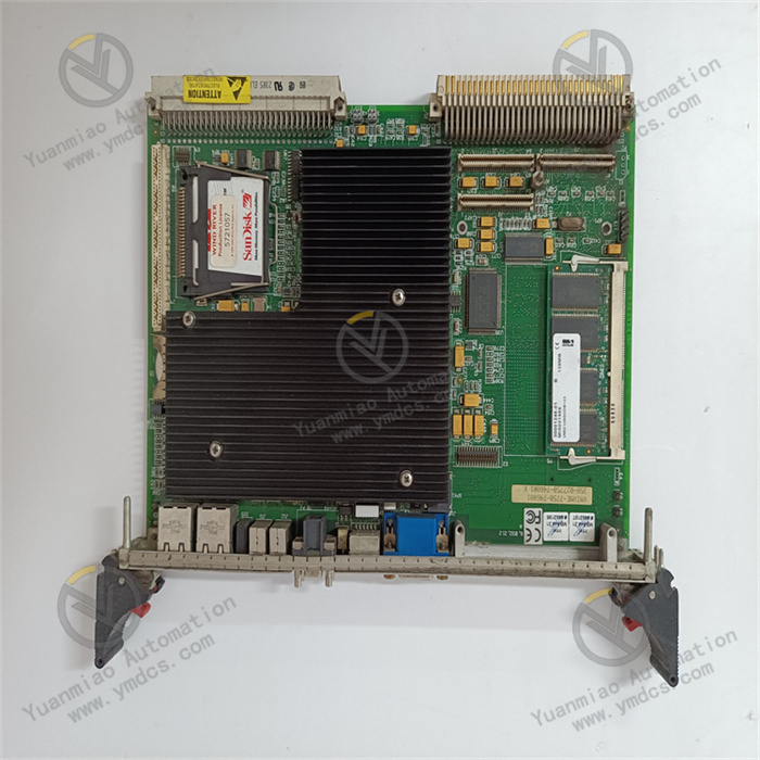
ABB CP405 1SAP500405R0001
I. Functional Positioning
The CP405 is a core communication module for ABB's AC 800M series controllers, primarily designed to enable multi-protocol data interaction and cross-network communication in industrial automation systems. It serves as a key component for building Distributed Control Systems (DCS) and Industrial Internet of Things (IIoT) architectures. Its core functions include:
Multi-Protocol Communication Gateway
Supports multiple industrial communication protocols (e.g., Profibus DP, Modbus RTU/TCP, Ethernet/IP, etc.), enabling interconnection and interoperability between devices using different protocols.
Data Forwarding and Processing
Parses, filters, and converts data formats across networks (e.g., unit conversion, protocol encapsulation) to ensure accurate transmission to target systems (e.g., PLCs, SCADA, cloud platforms).
System Expansion and Integration
As an expansion module for AC 800M controllers, it connects distributed I/O, third-party devices, or upper-level management systems, enhancing system compatibility and flexibility.
II. Technical Parameters
| Parameter | Description |
|---|---|
| Model | 1SAP500405R0001 (CP405) |
| Communication Protocols | - Profibus DP V1/V2 - Modbus RTU/TCP - Ethernet/IP - OPC UA - Extendable to other protocols (requires software licensing) |
| Interface Types | - 2× Ethernet ports (10/100/1000 Mbps, RJ45) - 1× Profibus DP port (DB9) - 1× RS-232/485 serial port (optional) |
| Processing Capability | - Built-in high-performance processor for real-time data processing and protocol conversion - Data throughput: ≥100 Mbps (protocol complexity-dependent) |
| Memory | - Program memory: 512 MB (Flash) - Data memory: 256 MB (RAM) |
| Operating Voltage | DC 24 V (±10%), supports redundant power input |
| Power Consumption | Approximately 12 W |
| Operating Temperature | -40°C ~ +70°C (industrial-grade wide temperature range) |
| Protection Level | IP20 (requires installation in control cabinets) |
| Dimensions (W×H×D) | Approximately 100 mm × 160 mm × 80 mm |
| Certifications | CE, ATEX (optional explosion-proof certification), IEC 61508 (functional safety, requires specific configuration) |
III. Working Principle
The CP405 acts as a protocol translator and data transfer hub, with the following workflow:
Protocol Parsing
Receives data from diverse networks (e.g., Profibus fieldbus, Modbus devices, Ethernet systems) and parses raw data (e.g., device addresses, register values, status bits) according to predefined protocol rules.
Data Processing
Filters, maps, and processes parsed data (e.g., unit conversion, threshold judgment) or converts formats (e.g., binary to decimal) to meet the input requirements of target systems.
Protocol Conversion
Repackages processed data into the protocol format of the target network (e.g., converting Profibus to Ethernet/IP) to ensure correct recognition by target devices (e.g., PLCs, SCADA systems).
Data Forwarding
Transmits converted data to target systems via Ethernet or serial ports, supporting bidirectional communication (e.g., remote control commands from upper-level systems to field devices).
Status Monitoring and Diagnosis
Built-in diagnostic functions real-time monitor communication link status (e.g., signal strength, error frame count), with fault feedback via indicator lights (e.g., LINK, ACT, ERR) or software logs.
IV. Application Scenarios
Industrial Automation Production Lines
- Scenario: Connects legacy devices (e.g., Modbus RTU-compatible sensors) with modern Ethernet control systems (e.g., AC 800M controllers) to achieve seamless integration of "traditional devices + modern systems."
- Value: Avoids system fragmentation due to protocol incompatibility and reduces upgrade costs.
Process Control and Energy Industry
- Scenario: Acts as a Profibus DP master to connect distributed I/O modules (e.g., ABB S800 I/O) in chemical/petroleum platforms while forwarding data to SCADA systems or cloud platforms via Ethernet.
- Value: Enables real-time monitoring and remote management of field data, supporting IIoT applications.
Power and Smart Grid
- Scenario: Collects data from relay protection devices via Modbus TCP in substations, converts it to OPC UA, and uploads it to Energy Management Systems (EMS).
- Value: Standardizes data formats from different vendors, enhancing grid monitoring compatibility and efficiency.
Hybrid Network Architecture Integration
- Scenario: Serves as a central communication hub in complex systems with Profibus, Ethernet/IP, and Modbus networks to enable multi-segment data interaction.
- Value: Simplifies system architecture, reduces the number of dedicated gateways, and lowers maintenance costs.
V. Operation and Maintenance Recommendations
Installation Key Points
- Physical Installation: Mount vertically on a DIN rail, ensuring ≥20 mm heat dissipation spacing between modules to avoid performance degradation due to high temperatures.
- Wiring Specifications:
- Use shielded cables for communication lines, keeping them away from power cables to reduce electromagnetic interference.
- Profibus networks require terminator resistor matching; Ethernet interfaces support redundant links (e.g., ring topology).
Parameter Configuration
Configure communication protocols, IP addresses, data mapping tables, etc., via ABB Control Builder M software.
- Example: To forward register data from a Profibus slave to a Modbus TCP master, establish a "source address → target address" mapping in the software.
Maintenance and Fault Troubleshooting
- Status Monitoring:
- PWR Light: Steady on indicates normal power supply; off requires checking power connections.
- LINK/ACT Lights: Flashing on Ethernet ports indicates data transmission; steady on or off may signal link faults (check network cables, switch ports).
- ERR Light: Steady on indicates module faults; read diagnostic logs via software (e.g., protocol parsing errors, memory overflow).
- Common Fault Handling:
- Communication Interruptions: Verify protocol parameters (e.g., baud rate, slave address) and test physical link connectivity (e.g., ping commands).
- Data Errors: Confirm data mapping tables and check for abnormal outputs from source devices (e.g., sensor failures).