Description
1. Overview
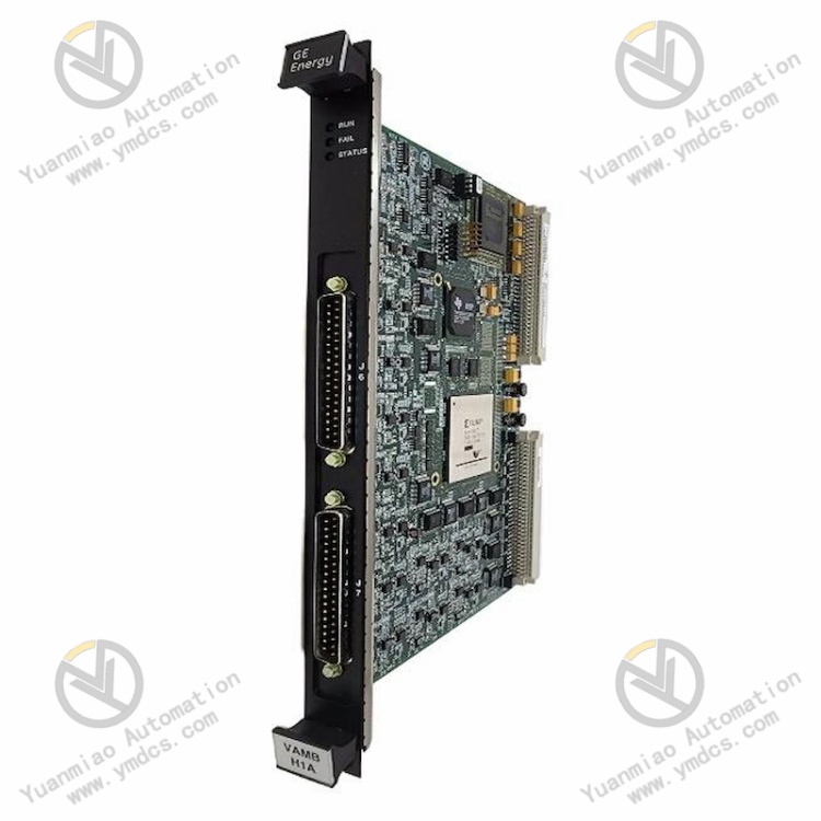
The IS215VAMBH1A is a dedicated acoustic monitoring mainboard for the Mark VI gas/steam turbine control system under GE (General Electric) Bently & Turbine Control. It belongs to the IS200/IS215 series core turbine‑control board cards, serving as a critical intelligent acquisition module for vibration‑acoustic monitoring, equipment fault prediction and unit condition diagnosis of large‑scale gas and steam turbines. Designed for mainstream heavy‑duty gas turbine models including Frame 6, Frame 7 and Frame 18, this board works together with the TAMB terminal daughter‑board to form a complete acoustic monitoring system. It is widely deployed for abnormal‑noise monitoring, mechanical fault early‑warning and refined unit condition management in thermal power plants, cogeneration plants, combined‑cycle power stations and industrial turbine‑driven units.
Integrated with high‑precision charge‑amplifier circuits, second‑order anti‑aliasing filter units and multiple independent signal‑acquisition channels, this board captures real‑time acoustic signals from turbine bodies, bearings and cavities, and accurately identifies latent faults such as abnormal unit noise, mechanical looseness, friction‑impact and incipient component failure. Fully compliant with GE original turbine‑control design standards and industrial control safety specifications, it supports the control‑system triple‑network redundant communication architecture. Featuring high acquisition accuracy, strong anti‑interference performance, low long‑term drift, hot‑swap capability and convenient maintenance, it is qualified for 7×24‑hour heavy‑duty continuous operation of turbine units. It is a precision core board for turbine condition monitoring, advance fault prediction and unplanned‑outage mitigation.
2. Functions and Features
2.1 Core Functions
Multi‑channel high‑precision acoustic‑signal acquisition: Equipped with 9 independent acoustic‑monitoring channels on a single board, it is engineered for abnormal‑noise signal acquisition of heavy‑duty gas and steam turbines. It synchronously collects acoustic‑vibration signals from unit cavities, bearing housings and cylinder casings, covering key acoustic‑monitoring points of turbines to realize full‑range unit condition perception.
Professional charge amplification and signal conditioning: Built‑in dedicated charge‑amplifier circuits and second‑order anti‑aliasing filter structures amplify, shape, denoise and filter weak acoustic‑sensor field signals. It effectively rejects high‑frequency clutter, power‑frequency interference and ambient noise to preserve the purity and acquisition accuracy of raw acoustic signals.
Autonomous line‑fault detection and diagnosis: Adopting a high‑impedance DC‑bias detection mechanism, it automatically identifies faults such as open‑circuit, poor contact, wire breakage and sensor failure between the TAMB daughter‑board and charge amplifier. Real‑time line‑abnormality alarms are reported to prevent invalid acquisition and data distortion.
Standard buffered signal output: Each channel provides independent buffered BNC standard output, delivering pure waveforms of raw input signals with DC‑bias removed. It can be directly interfaced with upper‑level analysis equipment, waveform recorders and diagnostic systems to support raw‑waveform traceability and refined fault analysis.
Triple‑network redundant stable communication transmission: Compatible with the ARCNET triple‑network redundant communication architecture of the Mark VI system, it achieves high‑speed, synchronous and reliable upload of acquired data. Mutual backup among multiple networks avoids communication interruption and data loss, ensuring complete and continuous unit monitoring data.
Early‑stage unit fault prediction and warning: By continuously monitoring variations in unit acoustic characteristics, it accurately detects latent faults including mechanical friction, component looseness, abnormal cavity vibration and incipient bearing damage. Early warning signals are output to provide data support for unit maintenance, hazard elimination and emergency shutdown.
Hot‑swap for rapid maintenance: Adopting LRU (Line‑Replaceable Unit) design, it supports non‑stop hot‑swap replacement with MTTR<5 minutes, greatly cutting fault‑downtime and meeting requirements for continuous power‑plant production and uninterrupted unit operation.
System interlock and configuration compatibility: Seamlessly compatible with the full GE Mark VI turbine‑control suite. It supports parameter configuration, custom threshold setting, status‑linked alarming and time‑series data storage, fitting the intelligent and refined unit condition‑management framework.
2.2 Product Characteristics
Superior acquisition accuracy and stability: Original precision circuit architecture delivers 0.1%‑level overall acquisition accuracy with excellent‑channel‑to‑channel consistency. Zero‑point drift and gain attenuation are negligible over long‑term operation, satisfying stringent high‑precision condition‑monitoring requirements for large turbines.
High integration for cabinet‑space saving: Nine monitoring channels are integrated on one board with high channel density. Compared with conventional split acquisition modules, it saves 40 % cabinet depth and reduces field cabling volume by 30 %, lowering system integration material and construction costs.
Industrial‑grade anti‑interference capability: Multi‑stage filtering, signal shielding and anti‑aliasing circuits suppress strong electromagnetic interference, power‑equipment harmonic interference and ambient noise in power‑plant environments. It maintains undisturbed signal acquisition under cabinet conditions of high temperature, vibration and complex electromagnetic fields.
Modular lightweight maintenance‑oriented design: Modular split architecture consisting of mainboard and TAMB daughter‑board enables independent disassembly‑and‑assembly with clear fault localization. A single technician can complete replacement and commissioning without dismantling the whole system for high maintenance efficiency.
Wide‑temperature long‑term reliable operation: Industrial‑military grade components undergo rigorous high‑low‑temperature, vibration and ageing tests. It tolerates alternating temperature, continuous vibration, dust and humidity in power‑plant conditions with low failure rate and long service life.
Standardized universal compatibility: Fully compatible with the full GE Mark VI control‑system family and Frame 6/7/18 heavy‑duty gas‑turbine range. Old and new boards are directly interchangeable with minimal post‑replacement commissioning for outstanding compatibility and versatility.
Visual status monitoring: Dedicated LED status indicators on the board intuitively display power supply, channel operation, communication and fault‑alarm status, enabling on‑site quick judgement of equipment operating conditions and fault points.
3. Technical Specifications
| Item | Specification |
|---|---|
| Model | IS215VAMBH1A |
| Product Series | GE IS200/IS215 Turbine‑Control Series |
| Device Type | Acoustic Monitoring Mainboard |
| Manufacturer | GE (General Electric, USA) |
| Compatible System | GE Mark VI Gas / Steam Turbine Control System |
| Applicable Units | Frame 6, Frame 7, Frame 18 Heavy‑Duty Gas Turbines |
| Number of Acquisition Channels | 9 independent acoustic acquisition channels |
| Acquisition Accuracy | 0.1 % high‑precision signal acquisition, excellent channel consistency |
| Signal‑Processing Architecture | Built‑in charge‑amplifier circuit + second‑order anti‑aliasing filter circuit |
| Output Interfaces | Independent buffered BNC output per channel |
| Line‑Detection Function | High‑impedance DC‑bias detection; open‑circuit and wire‑break fault diagnosis |
| Communication Architecture | ARCNET triple‑network‑redundant communication, high‑speed synchronous data transmission |
| Maintenance Features | Hot‑swap support, MTTR<5 min, LRU design |
| Matched Daughter‑Board | TAMB signal‑conditioning terminal daughter‑board |
| Operating Temperature | ‑20 ℃~+70 ℃ industrial wide‑temperature operation |
| Storage Temperature | ‑30 ℃~+80 ℃ |
| Ambient Humidity | 5 %~95 % RH, non‑condensing |
| Mechanical Features | High‑density‑channel design, modular split‑frame, front‑panel LED status indication |
| Operational Features | High‑precision acquisition, high anti‑interference, low drift, hot‑swap maintenance, triple‑network redundancy, early‑fault warning |
4. Working Principle
The IS215VAMBH1A acoustic‑monitoring board operates based on the core principles of weak acoustic‑signal acquisition, charge‑amplifier conditioning, filter‑based noise reduction and synchronous data transmission. Together with the TAMB terminal daughter‑board, it forms a complete turbine acoustic‑monitoring system to realize accurate monitoring and prediction of unit operational abnormal noise and mechanical faults.
During unit operation, field acoustic sensors collect faint vibration‑acoustic signals from key positions such as turbine casings, bearings and cavities. After preliminary shunting, voltage‑stabilization and protection processing on the TAMB daughter‑board, signals are fed into the IS215VAMBH1A mainboard. On‑board high‑sensitivity charge‑amplifier circuits precisely amplify faint charge‑mode sensor outputs, while second‑order anti‑aliasing filters remove invalid interference including high‑frequency electromagnetic noise, power‑frequency clutter and ambient noise, retaining pure unit acoustic‑characteristic waveforms.
Via the high‑impedance DC‑bias detection mechanism, the board continuously monitors front‑end signal‑loop conditions and triggers immediate alarms for open‑circuit, poor‑contact and sensor‑failure events. Conditioned standard acoustic signals are routed in two ways: buffered raw waveforms are output via independent BNC ports for external fine‑granularity waveform analysis and traceability; meanwhile, data parsing, feature extraction and threshold comparison are performed by the on‑board processing unit. Processed data is synchronously transmitted to the Mark VI main controller over the ARCNET triple‑network‑redundant bus.
Combining unit operating conditions, historical acoustic datasets and preset alarm thresholds, the main controller judges in real‑time potential hazards such as mechanical friction, component looseness, abnormal vibration and incipient component damage, and activates graded alarms and status logging. Hot‑swap online replacement is supported; replacement operations do not disturb overall system operation or acquisition on other channels, ensuring continuous stable performance of the unit monitoring system.
5. Application Scenarios
Heavy‑duty gas‑turbine condition monitoring: Applied to Frame 6/7/18 gas‑turbine units for real‑time acoustic monitoring of cavities, bearings and rotors. It captures abnormal noise during startup‑shutdown, load‑variation and steady‑state operation to realize early‑stage mechanical‑fault prediction.
Steam‑turbine equipment fault early‑warning: Deployed for acoustic monitoring of cylinder casings and bearing housings in thermal‑power and cogeneration steam‑turbine units. It identifies hidden defects such as internal friction, blade looseness and cavity resonance, mitigating risks of blade damage, shaft‑system failure and unplanned unit outages.
Intelligent O&M for combined‑cycle power stations: As a core monitoring unit of the Mark VI system, it supports unattended operation, condition‑based maintenance and refined management. Acoustic‑data trend analysis optimizes maintenance cycles and reduces O&M costs.
Industrial turbine‑driven‑unit monitoring: Used for condition supervision of turbine‑driven machinery and large prime‑movers in industrial plants, keeping track of mechanical health to guarantee stable continuous industrial production.
Retrofit of legacy turbine‑monitoring systems: Replaces older generation boards with low acquisition accuracy, missing noise‑rejection and no line‑self‑diagnosis. System architecture and field cabling remain largely unchanged for rapid improvement of fault‑prediction capability and monitoring stability.
Unit‑fault traceability and data analysis: Complete pure acoustic waveforms and time‑series records provide accurate data support for fault post‑mortem review, operating‑condition optimization, equipment‑life assessment and technical retrofits.
6. Common Faults and Troubleshooting
6.1 No data / acquisition failure on single‑channel or multiple‑channels
Causes: Damaged or failed front‑end acoustic sensor; faulty corresponding channel on TAMB daughter‑board; broken wire, poor contact or short‑circuit in signal circuit; damaged channel circuit on mainboard; incorrect channel‑acquisition parameter configuration.
Remedies: Troubleshoot sensors channel‑by‑channel and replace defective units; inspect TAMB daughter‑board channels and repair faults; test continuity of signal cables and terminals, tighten loose connections and replace damaged wiring; verify and correct channel‑acquisition configuration. If no data persists with intact external loops, the mainboard channel hardware is defective; replace the board.
6.2 Volatile measurement readings, chaotic waveforms, severe noise interference
Causes: Severe on‑site electromagnetic interference; damaged shielding or poor earthing of signal cables; degraded filter‑circuit performance; poor sensor contact; clutter coupled into signal loops.
Remedies: Inspect signal‑cable shielding integrity, re‑establish proper earthing and route cables away from power cables and variable‑frequency drives; secure sensor connections and mounting points; remove dust and contamination from the board and check filter‑circuit health; reboot to refresh acquisition firmware. Replace the board if interference cannot be eliminated.
6.3 System reports line‑open / signal‑loop‑abnormality alarms
Causes: Broken signal cable, oxidized or loose terminals; poor mating between mainboard and TAMB daughter‑board; abnormal sensor impedance or internal open‑circuit; faulty DC‑bias detection circuit on mainboard.
Remedies: Fully inspect signal‑loop cables and terminals, clean oxidation, tighten connections and repair broken points; re‑seat and secure the interface between mainboard and TAMB daughter‑board; measure sensor impedance and replace abnormal sensors. If alarms persist despite healthy loops, the on‑board detection circuit is defective; replace the board.
6.4 No waveform at BNC output, abnormal buffered‑signal output
Causes: Loose or damaged BNC connector; failed on‑board signal‑buffer circuit; channel‑acquisition function disabled; fault on receiving‑side equipment.
Remedies: Inspect BNC connection; tighten or replace damaged connectors; review configuration and enable signal‑output function; troubleshoot downstream waveform‑recording equipment. If output remains absent with correct configuration and external hardware, the buffer circuit is damaged; replace the board.
6.5 Communication dropout, no data upload, triple‑network communication anomaly
Causes: Loose or damaged ARCNET communication cables; incorrect communication address or baud‑rate settings; ageing communication module on board; system‑bus conflict or network interference.
Remedies: Inspect triple‑network communication cabling and reseat connectors; match communication parameters between board and Mark VI system; investigate bus conflicts and interference sources; restart board communication services. Replace the board if communication cannot be restored.
6.6 Persistent LED fault alarm, abnormal board operation
Causes: Abnormal or unstable cabinet supply voltage; dust accumulation and moisture ingress on board, circuit ageing; firmware hang‑up; defective hardware components.
Remedies: Test cabinet power supply and eliminate undervoltage, overvoltage and fluctuation risks; clear dust and moisture from board and backplane slots and improve cabinet ventilation; power‑cycle to reset firmware. Replace the original board if alarms remain after multiple resets, indicating hardware failure.