Description
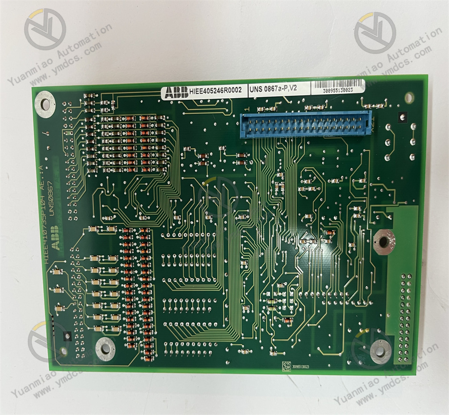
ABB UNS0867A-P,V1 HIEE405246R0001
I. Product Overview
Product Identification
- Type: UNS0867A-P
- Version: V1
- Global Material Number: HIEE405246R0001
- Product Series: AC 800M Series
- Product Category: Central Processing Unit (CPU) Module
Country of Origin: Sweden
Core Functions
This module serves as the core control unit of the AC 800M Programmable Logic Controller (PLC), acting as the “brain” of the controller rack, specially designed for demanding process automation applications.It executes control logic programmed in accordance with IEC 61131-3 standard languages (such as Structured Text, Function Block Diagram), manages I/O data exchange, and coordinates communication with engineering stations, Human-Machine Interface (HMI) and enterprise systems, featuring high-performance data processing and stable operational reliability.The module integrates a Profibus DP master interface, allowing direct connection to remote I/O stations without additional communication modules. It also supports fast scan cycles and powerful diagnostic functions, meeting both basic regulation control and complex batch/sequential logic control requirements, making it a key component ensuring efficient operation of automation systems.
Application Scenarios
Widely used in process automation control systems in thermal power generation, hydropower, oil and gas, chemical, mining and water treatment industries.It adapts to the control requirements of high-voltage induction motors, synchronous motors and generators, and is especially suitable for medium to large-scale control tasks with high demands on control accuracy and operational stability.It can be seamlessly integrated into the ABB System 800xA distributed control architecture to achieve unified management of process control, electrical control, safety and asset optimization.
II. Technical Specifications
| Parameter Category | Details |
|---|---|
| Electrical Specifications | CPU Type: 32-bit RISC processorApplication Memory: 1MB RAM (with battery backup)Communication Interfaces: 1×RS-232 (service port), 1×Profibus DP master (9.6kbps–12Mbps)Supported Protocols: Profibus DP, Modbus RTU (CI module required), EtherNet/IP (CI 854A required)I/O Capacity: Up to 16,000 I/O points (depending on configuration) |
| Physical Specifications | Dimensions (H×L×W): 263×58×28 mmNet Weight: approx. 0.4 kg (reference value for same series)Protection Degree: Board-level IP20 (cabinet protection required)Mounting: Modular mounting (suitable for AC 800M controller rack) |
| Environmental Adaptability | Operating Temperature: -20℃ to +60℃Storage Temperature: -40℃ to +85℃EMC Performance: Complies with industrial EMC standardsAmbient Humidity: 15%~85% (non-condensing) |

III. Installation & Maintenance Guide
Pre-installation Requirements
- Anti-static: An anti-static wristband must be worn before operation. Do not touch the board contacts (gold fingers) or electronic components with bare hands to avoid electrostatic damage to core components.
- Environment: Must be installed in a dust-free, non-condensing, well-ventilated control cabinet, away from strong heat sources (e.g., power modules), strong interference sources (e.g., inverters, high-voltage cables) and vibration sources, to ensure ambient temperature and humidity meet product specifications.
- Wiring Rules: Wiring must be done strictly according to electrical drawings to ensure correct and secure connections. Separate communication cables from power cables to reduce interference. Ground terminals must be securely connected to the system equipotential busbar to guarantee communication stability and equipment safety.
- Rack Compatibility: Ensure the module fits perfectly into the AC 800M controller rack and tighten mounting screws to avoid loose connections that affect data transmission and operation.
Routine Inspection
- Indicator Lights: Regularly check module status indicators. Normal operation shall comply with definitions in the product manual. Investigate immediately if alarm lights are steady or flashing.
- Temperature & Air Ducts: Check for abnormal surface temperature of the module. Clean cabinet filters to ensure unobstructed air ducts and prevent overheating alarms due to poor heat dissipation.
- Connection Tightness: Inspect all screw terminals and communication interfaces for looseness, oxidation or burning marks. Tighten or repair as needed.
- Battery Status: Regularly check the memory backup battery. Replace with the same specification if low on power to avoid program loss.
Periodic Maintenance
- Every 6 months: Clean the cabinet ventilation system and dust on the module surface; check cooling fan operation; inspect communication cable connections to ensure stable communication.
- Annually: Test electrical performance, communication speed and I/O data transmission accuracy with professional instruments; replace the memory backup battery; back up the module program and establish maintenance records documenting content, parameters and test results.
- Every 2 years: Perform a comprehensive inspection to identify potential faults and ensure performance meets operational requirements. Evaluate replacement if aging signs appear.
IV. Common Faults & Troubleshooting
| Fault Symptom | Possible Causes | Troubleshooting & Solutions |
|---|---|---|
| Module fails to start, no indicator lights | 1. No external power supply or abnormal voltage2. Poor contact between module and rack3. Internal fuse blown4. Core chip failure | 1. Measure input voltage and restore normal power2. Reinsert the module and tighten mounting screws for good contact3. Check internal fuse after power off; replace with same-specification fuse4. If above are normal, module hardware is faulty; repair or replace at factory |
| Unstable or no communication | 1. Loose or damaged communication cable2. Incorrect communication protocol settings3. Oxidized or damaged communication interface4. Signal loss due to strong interference | 1. Check communication cable, reconnect or replace good cable2. Verify protocol and address settings to match the system3. Clean communication interface; replace interface or module if damaged4. Optimize wiring away from interference sources; add shielding if needed |
| Abnormal I/O data transmission | 1. Communication fault between I/O and CPU module2. Incorrect program logic settings3. Damaged I/O points4. Fluctuating supply voltage | 1. Check I/O module connection; restart module to restore2. Review control logic and correct errors3. Test I/O performance; replace faulty I/O module4. Check supply voltage; install voltage stabilizer for stable power |
| Module overheat alarm / automatic shutdown | 1. Blocked cabinet ventilation, poor heat dissipation2. Ambient temperature over limit3. Damaged cooling fan4. Excessive module load | 1. Clean filters and dust; ensure unobstructed air ducts2. Improve cabinet cooling to lower ambient temperature3. Check cooling fan; replace faulty fan4. Review module load; optimize control logic to reduce load |