Description
1. Overview
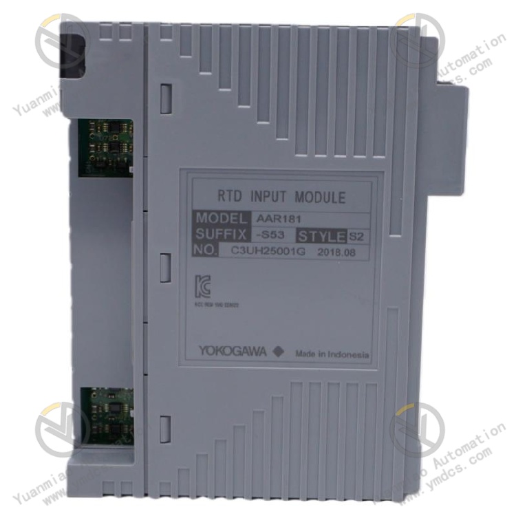
Yokogawa AAR181‑S50 S2 is an isolated RTD input module dedicated for Yokogawa CENTUM VP / CS3000 DCS systems. It belongs to Yokogawa’s high‑performance analog I/O hardware family and is designed for high‑precision temperature measurement in industrial fields. This is a standard non‑explosion‑proof module with 12‑channel fully‑isolated temperature acquisition. It supports mainstream industrial RTD sensors such as Pt100, and accurately acquires temperature analog signals from process equipment, pipelines and media. It serves as core input hardware for temperature monitoring, process interlock and equipment temperature measurement in process industries.
AAR181‑S50 S2 features per‑channel galvanic isolation, high‑precision signal conversion, wire‑break fault detection, low temperature drift and strong anti‑interference performance, suitable for 24‑hour continuous production in chemical, oil‑gas, power, metallurgical and other industries. As an original Yokogawa dedicated spare part with no universal substitute, it is widely used for temperature point expansion, legacy module replacement and control‑system upgrade. It is natively compatible with Yokogawa DCS backplanes, bus protocols and system configuration logic, requiring no secondary commissioning or calibration after replacement.
2. Functions and Features
2.1 Core Functions
Multi‑channel High‑precision RTD Acquisition: Equipped with 12 independent RTD input channels, supporting 3‑wire Pt100 RTD. It synchronously collects multi‑point field temperature signals to satisfy temperature monitoring for plant equipment, pipelines, tanks and process media.
Per‑channel Complete Galvanic Isolation: Each channel is electrically isolated from one another. Signal failure, line interference or ground anomaly on one channel will not affect other measurement points, eliminating temperature data jump and distortion caused by crosstalk and common‑mode interference.
Automatic Wire‑break Fault Diagnosis: Built‑in intelligent circuit detection monitors open‑circuit, poor contact and sensor damage of RTD loops in real time, and automatically reports wire‑break alarms with upper/lower limit judgement for accurate fault localisation and reduced maintenance workload.
High‑precision Signal Conversion & Calculation: High‑resolution AD converter achieves accurate conversion from resistance value to temperature reading. Low temperature drift and low error ensure stable long‑term performance, meeting accuracy requirements for precise temperature control and energy metering.
Signal Filtering and Anti‑interference Processing: Multi‑stage digital filtering and waveform‑shaping algorithms suppress electromagnetic interference, line noise and signal jitter, delivering stable, authentic and reliable temperature data under harsh industrial conditions.
High‑speed Bus Data Communication: High‑speed communication with controller via dedicated DCS backplane bus. It uploads channel temperature data, module status and fault alarms, and downloads configuration parameters to guarantee real‑time and consistent data transmission.
2.2 Product Features
Industrial‑grade High Accuracy & Stability: Industrial‑grade components and precision sampling circuitry deliver minimal temperature drift and excellent repeatability for continuous long‑run operation, complying with high‑precision process control standards for chemical and power industries.
Robust Anti‑interference Isolation Design: Per‑channel isolation mitigates electromagnetic interference from variable‑frequency drives and high‑voltage equipment, and prevents measurement anomalies induced by ground‑potential difference and crosstalk for heavy‑interference field environments.
Original Plug‑and‑play without Commissioning: Standard slot‑mount form‑factor for Yokogawa cabinets. Backplane interface, communication protocol and electrical parameters are fully compatible with CENTUM VP and CS3000. No configuration modification or on‑site calibration is needed upon replacement.
Harsh‑condition Adaptability: Optimised wide‑temperature circuitry tolerates temperature swing, dust, humidity and mechanical vibration for reliable non‑stop field operation with low failure rate.
High‑density Integrated Channel Design: Twelve temperature channels on single module save cabinet space and hardware footprint, lowering procurement and maintenance costs.
3. Specifications
| Parameter Item | Technical Specification |
|---|---|
| Model | AAR181‑S50 S2 |
| Device Type | 12‑Channel Isolated RTD Input Module |
| Input Channels | 12 independent isolated temperature channels |
| Supported Sensor | Standard 3‑wire Pt100 RTD |
| Isolation | Galvanic isolation between channels; channel‑to‑bus isolation |
| Fault Detection | Automatic detection & alarm for wire break, poor contact and sensor fault |
| Data Update Cycle | 1 s |
| Temperature Drift Accuracy | ±120 mΩ / 10 ℃ |
| Power Supply | DCS backplane bus powered |
| Operating Temperature | 0 ℃ ~ +60 ℃ (industrial standard range) |
| Ambient Humidity | 5%‑95%RH, non‑condensing |
| Explosion‑proof Rating | Standard version, no explosion‑proof certification |
| Installation | Standard slot‑mount in DCS cabinet |
| Applicable Systems | Yokogawa CENTUM VP / CS3000 DCS |
4. Working Principle
Yokogawa AAR181‑S50 S2 implements closed‑loop temperature measurement workflow: Field Signal Input → Isolation Protection → Resistance Sampling → Filtering & Shaping → AD Conversion → Data Calculation & Transmission → Fault Self‑diagnosis.
Resistance signals from field Pt100 RTD sensors enter individual module channels and pass through front‑end isolation circuits, which suppress external interference, ground‑potential difference and abnormal electrical signals to protect internal sampling hardware.
Isolated resistance signals go to high‑precision sampling units for real‑time resistance acquisition. Multi‑stage digital filtering removes electromagnetic noise and signal jitter. On‑board high‑resolution AD chips convert analog resistance values into digital data. Embedded temperature‑conversion algorithms calculate corresponding temperature readings. Meanwhile, loop continuity is continuously checked to generate alarms for wire break or sensor failure.
Processed temperature data and module status are transmitted over backplane bus to DCS controllers for process monitoring, parameter regulation and interlock logic. Channels operate independently; faulty channels are isolated without disturbing other points. Continuous self‑diagnosis covers power supply, circuit condition and signal links to ensure accurate, stable and consistent temperature acquisition.
5. Application Scenarios
Chemical Process Temperature Control Systems: Temperature acquisition for reactors, heat exchangers, pipelines and storage tanks in refineries, fine‑chemical and coal‑chemical plants. Provides accurate temperature inputs for process control, interlock protection and safety monitoring to stabilise chemical production.
Oil & Gas Automation Systems: Temperature monitoring for equipment and media in oilfields, gas fields, LNG plants and long‑distance pipelines. Adapts to harsh outdoor interference‑prone environments for round‑the‑clock reliable temperature measurement and safe production & transportation.
Power‑plant Control Systems: Temperature measurement and monitoring for boilers, steam turbines, auxiliary machinery and thermal pipelines. Supports load regulation, equipment condition monitoring and early‑fault warning for safe continuous power‑plant operation.
Metallurgy, Pharmaceutical & Water‑treatment Systems: Temperature monitoring for metallurgical furnaces, pharmaceutical reactors and water‑treatment process equipment. Suited for high‑accuracy, high‑stability process‑control applications to keep production parameters within specifications.
Legacy DCS Maintenance & Expansion: Fully compatible with older CENTUM series DCS. Direct replacement of faulty or aged temperature modules without rewiring or configuration changes enables fast I/O expansion and hardware upgrade.
6. Common Faults and Troubleshooting
6.1 No temperature reading, abnormal point display
Fault Causes: Defective RTD sensor; open‑circuit / poor field wiring; loose channel terminals; damaged module sampling channel; abnormal bus communication.
Solutions: Inspect on‑site RTD sensor and measure resistance value to verify health; check continuity and tightness of temperature‑measurement wiring; check module slot contact; power off, clean edge connectors and re‑seat module. If symptoms persist after eliminating external causes, the module channel is damaged; replace with original AAR181‑S50 S2.
6.2 Fluctuating / jumping temperature readings
Fault Causes: Severe on‑site electromagnetic interference; improper cable shielding & earthing; corroded or loose terminals; ageing filter circuit; sampling‑accuracy drift.
Solutions: Rectify signal shielding and earthing to reduce EMI; tighten and clean terminals, replace degraded cables; improve cabinet cooling to avoid high‑temperature drift. Replace spare module if fluctuation cannot be eliminated due to hardware performance degradation.
6.3 Frequent channel wire‑break alarms
Fault Causes: Poor RTD loop contact; intermittent ageing wiring; bad sensor solder joints; abnormal module wire‑break‑detection parameters.
Solutions: Thoroughly inspect field wiring and sensors, replace defective components; retighten all terminals to eliminate loose connections; reset module acquisition parameters. Replace module if alarms persist after ruling out external faults, indicating defective detection circuitry.
6.4 Large temperature deviation, loss of measurement accuracy
Fault Causes: Long‑term parameter drift; ageing AD sampling circuit; degraded channel isolation performance; ambient‑temperature impact on sampling.
Solutions: Calibrate channel accuracy using precision resistance source and compare deviation; check environmental interference and external equipment. Replace original module once internal drift or sampling failure is confirmed to restore measurement accuracy.
6.5 Module communication failure, no data for all channels
Fault Causes: Poor backplane‑bus contact; abnormal firmware execution; cabinet power‑supply anomaly; overall module hardware failure.
Solutions: Inspect cabinet backplane interface and power supply; power‑cycle module and system to reset firmware; clean slot and bus contacts and re‑install module. Replace original module if communication failures recur.