Description
1. Overview
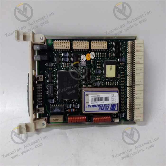
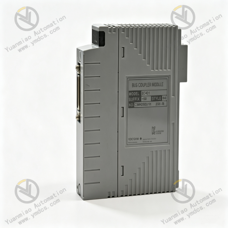
Yokogawa EC401‑50 S3 is a dedicated S3 bus coupler module for Yokogawa CENTUM VP and CS3000 DCS systems. It is core bus communication hardware and a pivotal component of the control‑system bus architecture. Designed for S3 field‑bus segment coupling, signal repeater and segment expansion, this is a standard non‑explosion‑proof general‑purpose module. It performs signal coupling, isolated forwarding and data exchange between multiple S3 bus segments, ensuring stable communication links among DCS I/O modules, field control stations and controller units.
EC401‑50 S3 provides bus isolated repeater, segment expansion, communication error correction, anti‑interference transmission and link self‑diagnosis. It effectively addresses issues including over‑long bus segments, excessive nodes, signal attenuation and cross‑segment interference in large‑scale plants. It is suitable for 24‑hour non‑stop control in chemical, oil‑gas, power and metallurgical process industries. As an original Yokogawa bus spare part with no universal alternative, it is widely used for bus architecture expansion, legacy bus‑module replacement and communication‑link upgrade of DCS systems. It natively supports full Yokogawa S3 bus protocols and cabinet back‑plane architecture. It can be commissioned directly without re‑configuration or bus commissioning after replacement.
2. Functions and Features
2.1 Core Functions
S3 Bus Segment Coupling & Interconnection: As a dedicated bus coupling unit, it realises reliable coupling and data exchange between two or more S3 bus segments. It connects communication links across different I/O segments and field control stations, consolidates distributed bus nodes and builds a complete and stable system bus network.
Bus Signal Repeater, Amplification and Compensation: For signal attenuation and waveform distortion caused by long‑distance bus transmission, it shapes, amplifies and regenerates S3 bus signals. It effectively extends bus transmission distance and improves communication stability for remote segments.
Bus Galvanic Isolation and Anti‑crosstalk: Built‑in galvanic isolation between bus segments. Interference, short‑circuit or abnormal signals on one segment cannot propagate to other segments, eliminating system‑wide communication jitter, disconnection and packet loss triggered by bus crosstalk.
Intelligent Bus Self‑diagnosis and Alarm: Continuously monitors bus link status, signal quality, segment faults and module anomalies. It accurately identifies bus open‑circuit, signal interference, segment conflict and communication timeout, uploads real‑time system alarms and accelerates fault location.
High‑capacity Bus Node Expansion: Breaks the node‑count limit of a single S3 bus segment. It expands system bus loading capacity via segment coupling, allowing more I/O modules, smart instruments and control nodes to be connected to satisfy measurement‑point expansion and system‑upgrade requirements of large‑scale plants.
High‑speed Bus Data Forwarding & Exchange: Supports high‑speed S3 bus transmission. It forwards controller commands, I/O measurement‑point data and device status in real time, ensuring low‑latency, low‑packet‑loss and high‑synchronisation bus transmission to support real‑time control logic of the DCS.
Redundant Bus‑architecture Compatibility: Natively supports DCS redundant bus configuration and bumpless redundant‑link switching. Failure of one link will not disrupt the whole bus network, maintaining uninterrupted communication for critical process control.
2.2 Product Features
Industrial‑grade Highly‑stable Bus Transmission: Adopts dedicated bus‑processing chip and signal‑shaping circuit with strong error‑correction and ultra‑low packet‑loss rate. No bus stalling or disconnection occurs during long‑term continuous operation for round‑the‑clock industrial control.
High‑anti‑interference Bus Isolation Design: Galvanic‑isolation architecture between segments suppresses electromagnetic interference, ground‑potential difference and surge. It isolates interference originating from different plant sections and guarantees stable bus operation under complex industrial conditions.
Plug‑and‑play, Configuration‑free Compatibility: Fully compatible with S3‑bus‑based Yokogawa CENTUM VP and CS3000 systems. Bus protocol, electrical parameters and back‑plane interface match perfectly. No system‑configuration modification or bus‑parameter tuning is required when replacing legacy modules.
Compact High‑density Design: Modular compact form‑factor for easy installation without occupying excessive cabinet space. It simplifies DCS bus layout and reduces O&M and upgrade costs.
Long‑term Adaptability for Harsh Conditions: Reinforced industrial components and anti‑ageing circuits withstand dust, humidity, vibration and temperature swings. It offers excellent environmental adaptability and low failure rate for non‑stop process‑industry service.
3. Specifications
| Parameter Item | Technical Specification |
|---|---|
| Model | EC401‑50 S3 |
| Device Type | S3 Bus Coupler Module |
| Supported Bus | Yokogawa proprietary S3 field bus |
| Core Functions | S3 bus‑segment coupling, signal repeating, isolated expansion, fault self‑diagnosis |
| Bus Transmission Characteristics | Signal shaping & amplification, data error correction, low‑latency forwarding |
| Isolation Feature | Galvanic isolation between multiple segments to prevent bus crosstalk |
| Power Supply | System cabinet back‑plane bus powered |
| Operating Temperature | 0 ℃ ~ +60 ℃ (standard industrial condition) |
| Ambient Humidity | 5%‑95%RH, non‑condensing |
| Explosion‑proof Rating | Standard version, no explosion‑proof certification |
| Installation | Standard slot‑mount inside DCS cabinet |
| Overall Dimensions | 130 × 129.5 × 32.8 mm |
| Weight | 0.24 kg |
| Applicable Systems | Yokogawa CENTUM VP / CS3000 DCS control systems |
4. Working Principle
Yokogawa EC401‑50 S3 bus coupler operates under closed‑loop workflow: Bus Signal Reception → Galvanic Isolation Protection → Signal Shaping & Regeneration → Data Error‑correction & Forwarding → Link Self‑diagnosis & Alarm.
Multiple independent S3 bus segments are connected to respective coupler ports. Incoming bus signals first pass built‑in galvanic‑isolation circuits to block cross‑segment electrical interference, ground‑potential difference and surge, preventing fault propagation across segments.
Isolated raw bus signals enter the dedicated bus‑processing unit. Signal amplification, waveform shaping and error‑correction regeneration are performed to remedy signal attenuation, waveform distortion and noise caused by long‑distance transmission, ensuring data integrity and accuracy. Following S3 bus protocol rules, the module implements data exchange, command forwarding and status synchronisation across segments to realise data communication among multi‑segment I/O modules, field devices and controllers, expanding bus node capacity and transmission range.
The module continuously monitors port link status, signal quality, data transmission and self‑operating condition. Upon detection of bus open‑circuit, signal anomaly, segment conflict or communication timeout, it latches the faulty segment, isolates the defective link and raises DCS system alarms to avoid total bus collapse triggered by single‑segment failure. Bumpless link switching is supported under redundant configuration to maintain stable, continuous and efficient DCS bus operation.
5. Application Scenarios
Large‑scale‑chemical‑plant DCS Bus Expansion: Multi‑section bus networking for refineries, coal‑chemical and fine‑chemical facilities. Resolves single‑segment constraints on node quantity and transmission distance, realises multi‑section segment coupling and expansion, and guarantees stable communication of plant‑wide process points.
Oil‑gas Long‑distance Automation Networking: Distributed‑measurement‑point bus networking for oilfields, gas fields, LNG plants and long‑distance pipelines. Signal repetition compensates long‑haul transmission loss and mitigates field‑interference‑induced bus instability to ensure real‑time upload of remote‑point data.
Power‑plant Control‑system Bus Deployment: Multi‑zone bus networking for boiler, steam turbine and auxiliary‑control systems. It isolates electrical interference from different equipment zones, suppresses crosstalk generated by variable‑frequency and high‑voltage apparatus, and secures stable unit‑control‑bus operation.
Anti‑interference Retrofit for Harsh Conditions: For high‑interference sites such as metallurgy and building‑material plants. Galvanic isolation and signal regeneration improve transmission quality and resolve communication faults including bus disconnection, packet loss and intermittent measurement‑point dropout.
Legacy DCS Bus Maintenance & Upgrade: Compatible with legacy Yokogawa CS3000 and CENTUM VP systems. Direct replacement of aged or faulty bus‑coupler modules eliminates hidden communication risks without bus rewiring or configuration change, enabling rapid bus‑performance optimisation.
6. Common Faults and Troubleshooting
6.1 Unstable system‑wide bus communication, frequent measurement‑point flicker
Fault Causes: Ageing module signal‑shaping circuit; severe bus signal attenuation; excessive segment interference; degraded module isolation performance; mismatched bus terminating resistance.
Solutions: Check terminating‑resistance configuration of each S3 segment and resolve impedance mismatch. Inspect bus shielding and earthing to eliminate external electromagnetic interference. Reboot module to reset bus links. If communication jitter persists after eliminating external factors, module hardware performance is degraded; replace with original EC401‑50 S3.
6.2 One bus segment offline, total data loss for associated points
Fault Causes: Damaged corresponding module bus port; open‑circuit segment wiring; loose bus connector; faulty port communication circuit.
Solutions: Inspect wiring and connectors of the faulty segment section‑by‑section to eliminate open‑circuit and loose connection. Perform cross‑port test to locate module‑port failure. Clean module edge‑connector and slot contacts and re‑seat firmly. Replace original module when hardware port damage is confirmed.
6.3 Bus packet loss, excessive command‑response latency
Fault Causes: Abnormal module error‑correction function; distorted bus signal; firmware anomaly after long‑time operation; overloaded bus segment.
Solutions: Audit bus‑node loading to avoid overloading one segment. Rectify wiring‑related interference. Power‑cycle module to refresh firmware status. Replace bus coupler if latency and packet loss cannot be recovered.
6.4 Recurring system alarms for bus‑coupler module fault
Fault Causes: Back‑plane power‑supply fluctuation; poor slot contact; internal module‑circuit failure; firmware abnormality.
Solutions: Verify cabinet back‑plane voltage and bus interface to rule out power‑supply faults. Clean module gold‑finger and slot contacts and re‑install securely. Restart system bus service to reset module status. Replace spare module if alarms keep recurring, indicating hardware failure.
6.5 Bus‑segment coupling failure, no data exchange across segments
Fault Causes: Failed module coupling function; abnormal port protocol; segment‑parameter conflict; module hardware‑logic fault.
Solutions: Verify bus‑parameter settings of each segment and eliminate parameter conflicts. Reboot module to re‑negotiate bus protocol. Replace original EC401‑50 S3 if inter‑segment communication still fails with no external‑configuration error, indicating damaged coupling circuit.