Description
1. Product Overview
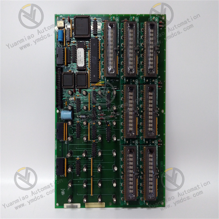
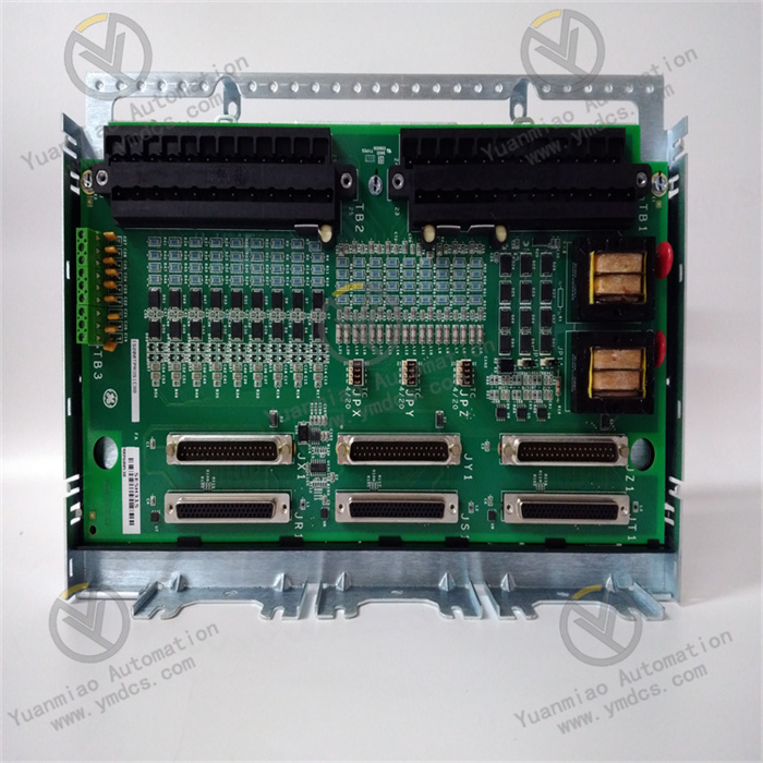
IS200TRLYH2EAA is a 12-channel solid-state relay (SSR) output terminal board, belonging to the IS200 series of I/O terminal cards. It is specially matched with Mark VI/Mark VIe control systems for gas turbines, steam turbines and power plant BOP auxiliary equipment. It converts digital logic commands sent by the main CPU into passive switching drive signals to control field loads including solenoid valves, contactors, alarm indicator lamps and remote valve actuators.
2. Technical Features
12 normally open solid-state outputs for long service life and maintenance-free operation
All channels adopt single normally open (NO) solid-state relays with no risk of mechanical contact ablation or adhesion. Capable of enduring frequent switching, they deliver much faster response than mechanical relays. Ideal for frequent sequential actions and high-frequency interlock loops of power units, they significantly reduce on-site card failure rates.
Independent isolated feedback per channel for output loop diagnosis
Each of the 12 channels is fitted with an independent isolated output voltage feedback circuit. The I/O processor reads feedback voltage via the JA1 interface to judge relay actuation status, wire breakage or load short-circuit in real time. Remote channel diagnosis and fault localization are available through ToolboxST software without on-site disassembly and circuit inspection.
Compatibility with simplex/TMR dual architectures for safety redundant systems
It works with regular simplex single-controller systems as well as TMR triple modular redundant turbine safety systems. Under TMR configuration, output is realized through voting of three control signals, meeting SIL requirements for high-safety loops such as unit emergency shutdown and fuel cut-off. Drive scheduling is uniformly managed by VCRC and VCCC I/O processors.
Comprehensive surge suppression with strong immunity to heavy electromagnetic interference in power plants
An integrated surge absorption circuit consisting of on-board metal film resistors, Zener diodes and absorption capacitors suppresses counter electromotive force from solenoid coils and power grid voltage spikes. It prevents breakdown of SSR chips caused by high-voltage surges and interference with backplane communication, accommodating harsh EMI conditions triggered by frequency converters and large motor startup/shutdown in power stations.
Fail-Safe power-on design
All solid-state relays remain open and de-energized by default upon power-up. In case of backplane communication interruption, cable disconnection or card power loss, all outputs cut off immediately. This ensures solenoid valves de-energize and reset, and actuators return to safe positions, eliminating equipment hazards arising from unintended actions caused by faults.
Standard VME board form factor for universal cabinet compatibility
3. Hardware & Electrical Specifications
3.1 Basic Hardware Information
| Parameter Item | Detailed Specification |
|---|---|
| Full Model | IS200TRLYH2EAA |
| Brand & Origin | General Electric (GE) |
| Product Type | Solid-State Relay (SSR) Output Terminal Board |
| Compatible Systems | Mark VI, Mark VIe Speedtronic Turbine Control Systems |
| Channel Quantity | 12 independent switching outputs |
| Contact Configuration | All normally open (NO); no normally closed contacts |
| Connectors | JA1 main signal D-Sub interface, 4 female cable sockets onboard |
| On-board Components | SSR solid-state relays, fuses, jumper terminals, metal film resistors, absorption capacitors, transient voltage suppression diodes |
| Mounting Method | Fixed installation in VME cabinet slots; DIN rail mounting available with optional bracket |
| Overall Dimensions | Width 178 mm × Height 330.2 mm |
| Gross Weight | Approximately 0.8~0.95 kg |
3.2 Electrical Load Parameters (Rated 24 VDC Operating Condition)
- Operating Power Supply: 24 VDC direct current on the system control side
- Rated Load: Maximum load resistance of 4.5 kΩ under 24 VDC; each channel supports low-power resistive DC loads including DC solenoid valves and indicator lamps
- Applicable Loads: DC inductive loads (coil-type loads) are prioritized; onboard TVS diodes absorb counter electromotive force
- Loop Protection: Independent fuse per channel for current limiting to prevent burnout of the entire card due to load short-circuit
- Feedback Loop: Isolated sampling of output-side voltage for each channel; voltage signals are transmitted to the I/O controller for status judgment
3.3 Environmental Specifications
- Operating Temperature: -30℃ ~ +65℃
- Storage & Transportation Temperature: -40℃ ~ +70℃
- Operating Humidity: 5%~95% RH, non-condensing
- Vibration Resistance: Complies with IEC industrial vibration standards for power plant cabinets, resisting long-term low-frequency vibration induced by fans and pumps
- EMC Performance: Tolerates electrostatic discharge, radio frequency interference and power harmonics, adapting to strong electromagnetic environments with high-power equipment in power plants
4. Working Principle
Switch Execution: When the card receives high-level drive signals, SSRs of corresponding channels conduct and energize external 24 VDC load circuits; SSRs turn off and loads power off once drive signals disappear.
Status Feedback: Independent isolated sampling circuits on each channel collect load-side voltage in real time and transmit on-off status to the I/O card. Upper computer software displays channel status including ON/OFF/open circuit/short circuit in real time.
5. Application Scenarios
Sequence Startup and Shutdown Control of Gas/Steam Turbines
12 channels perform stepwise sequential actions to drive various solenoid valves (fuel gas valves, purge valves, vent valves) during unit purging, ignition, speed acceleration and grid connection.
Interlock Control of Power Plant BOP Auxiliary Equipment
Realize remote start/stop, fault interlock trip and drive of audible-visual alarm loops for boiler fans, water pumps, oil pumps and cooling systems.
Protection Alarm Output for Power Units
Hard-contact alarm outputs triggered by protection actions such as overspeed, overtemperature, high vibration and abnormal pressure, driving field alarm lamps, buzzers and remote DCS dry contacts.
Retrofit & Replacement of Spare Parts for Legacy Mark VI Systems
Fully compatible with older TRLYH series terminal boards. No cabinet rewiring or program modification is required during replacement. It replaces aging mechanical relay cards and reduces equipment failures caused by relay contact adhesion.
Control Inside Explosion-Proof Cabinets for Chemical Plants and Distributed Energy Gas Turbines