Description
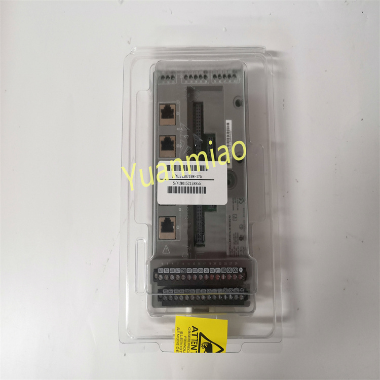
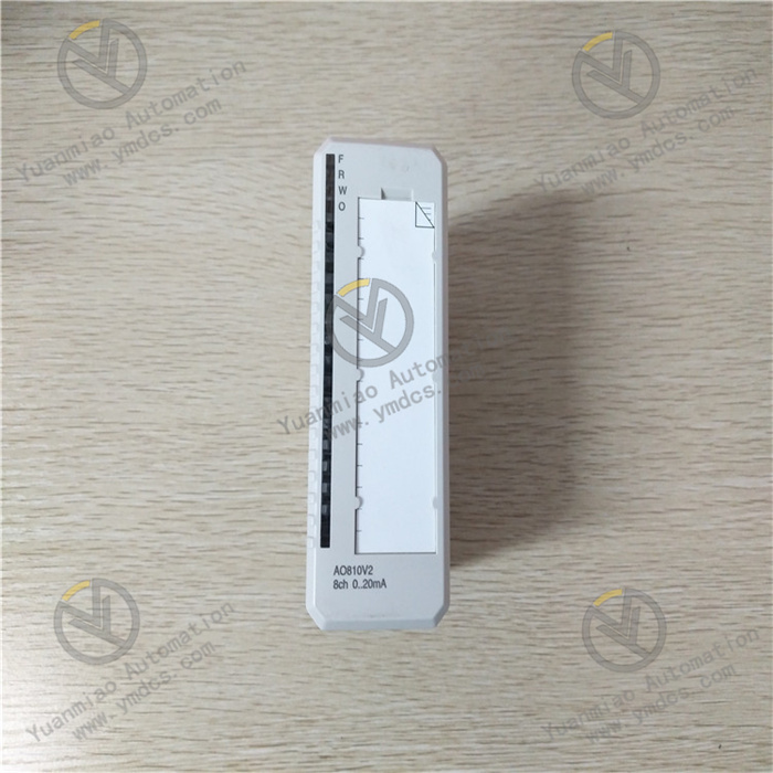
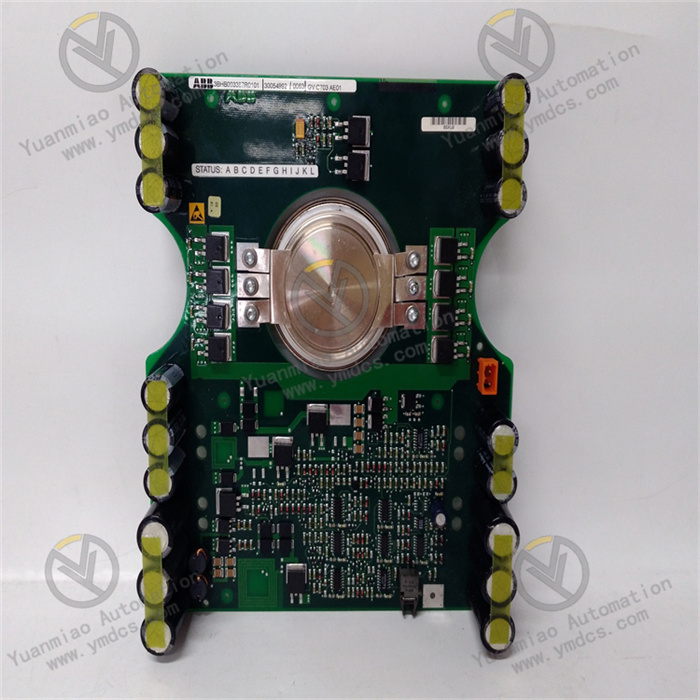
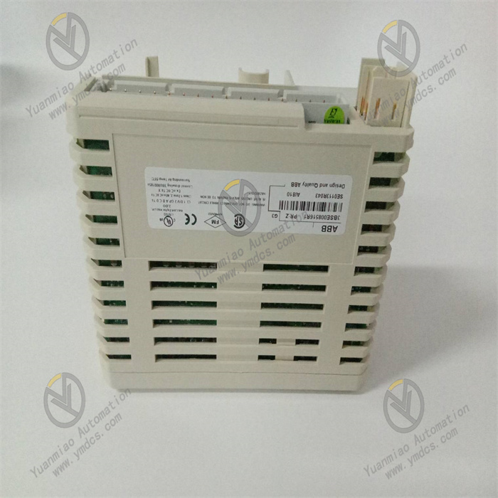
ABB AI810 3BSE008516R1
The ABB AI810 3BSE008516R1 is an analog input module. As a core I/O component of the AC 800M series distributed control system (DCS), it is widely used in industrial fields such as electric power, chemical engineering, metallurgy, and papermaking, thanks to its multi-channel high-precision acquisition, wide signal adaptation range, and high-reliability design. It undertakes the tasks of collecting and preprocessing continuous process parameters such as temperature, pressure, flow rate, and liquid level, and solves the problems of accurate capture of analog signals and anti-interference in complex industrial on-site environments. Its core advantages lie in the adoption of 24-bit ΔΣ A/D conversion technology and channel-level isolation design. While realizing 8-channel synchronous acquisition, it ensures a measurement accuracy of ±0.02% FS. It can seamlessly interface with ABB AC 800M controllers and third-party compatible systems, constructing a process monitoring link of "on-site perception - accurate acquisition - stable transmission". It provides reliable data support for the precise regulation of industrial process control and is a key acquisition component in industrial automation control systems.
- Equipped with 8 independent analog input channels, supporting switching between single-ended or differential input modes.
- Adopts a 24-bit ΔΣ A/D converter, with an adjustable sampling rate of 10Hz~1000Hz per channel, and a maximum sampling rate of 1000Hz for a single channel.
- Measurement accuracy is ±0.02% FS (at 25℃ ambient temperature), and the accuracy within the full temperature range is ±0.05% FS (-40℃~70℃).
- Linearity ≤0.01% FS, hysteresis error ≤0.005% FS, ensuring the accuracy of collected data.
- Supports input of multiple types of analog signals, including current signals (4~20mA DC, 0~20mA DC), voltage signals (0~5V DC, 1~5V DC, 0~10V DC), thermocouple signals (Types K, J, T, E, S, B, R, N), RTD signals (Pt100, Pt1000, Cu50, Cu100), and millivolt signals (0~100mV DC).
- Input impedance: ≥10MΩ for voltage signals, ≤100Ω for current signals, ≤10Ω for RTD signals.
- Equipped with a sensor open-circuit detection function, which can quickly identify open-circuit faults of thermocouples/RTDs.
- Adopts a channel-level isolation design. The isolation voltage between channels and between channels and the backplane bus is ≥500V AC (50Hz, lasting for 1 minute), and the isolation resistance is ≥1000MΩ (500V DC).
- Common-mode rejection ratio (CMRR) ≥120dB (50Hz/60Hz), differential-mode rejection ratio (DMRR) ≥80dB.
- Built-in 16th-order digital filtering and hardware filtering circuits. The filtering frequency band can be configured via software, effectively suppressing qualitative interference and high-frequency noise.
- Electromagnetic compatibility complies with EN 55032 Class B and IEC 61000-4-6 standards, with anti-RF interference capability ≥20V/m (80MHz~2GHz).
- Supports the PROFIBUS DP-V1 bus protocol and communicates with the AC 800M controller through the CI854/CI858 bus interface module.
- The bus data update cycle is ≤1ms (with 8 channels fully loaded), supporting cyclic and acyclic data transmission.
- Powered by a 24V DC power supply, with an input voltage range of 19.2V DC~28.8V DC and a typical input of 24V DC.
- Module power consumption ≤5W (with 8 channels fully loaded).
- Equipped with power reverse connection protection and overvoltage protection functions to ensure power supply safety.
- Operating temperature range: -40℃~70℃; storage temperature range: -40℃~85℃.
- Relative humidity: 5%~95% (condensation allowed, with a built-in anti-condensation heating circuit).
- Vibration resistance complies with IEC 60068-2-6 standard (10Hz~2000Hz, acceleration 5g); shock resistance complies with IEC 60068-2-27 standard (25g, 11ms half-sine wave).
- Protection class: IP20 (modular type), suitable for installation in control cabinets.
- Mean Time Between Failures (MTBF) ≥1,500,000 hours, supporting 24/7 continuous operation.
- Adopts a high-precision ΔΣ A/D conversion chip and a dedicated signal conditioning circuit, with a measurement accuracy of ±0.02% FS, enabling accurate capture of small parameter changes in industrial processes (such as 0.01mA current fluctuations).
- The 8 channels support synchronous sampling, with a sampling error ≤10ns, ensuring the time consistency of multi-measurement point parameters and providing accurate data for the analysis and control of multi-variable coupled processes.
- The accuracy remains at ±0.05% FS within the full temperature range, with a temperature drift of only 50ppm/℃, avoiding acquisition deviations caused by changes in ambient temperature and adapting to high and low-temperature industrial scenarios.
- Supports input of almost all commonly used industrial analog signals such as current, voltage, thermocouple, RTD, and millivolt. It can directly connect to different types of on-site instruments such as pressure transmitters, temperature sensors, and flow sensors without additional signal converters, simplifying system integration.
- The channel signal type, range, and filtering parameters can be quickly configured through the ABB Control Builder M configuration software. It supports independent channel configuration, and the same module can collect different types of signals simultaneously, adapting to complex multi-parameter acquisition scenarios.
- Built-in thermocouple cold-junction compensation circuit with a compensation accuracy of ±0.1℃, ensuring the accuracy of temperature measurement.
- Adopts a channel-level optoelectronic isolation design, with each channel independently isolated. It can effectively cut off cross-interference between channels and ground loop interference, and is particularly suitable for industrial sites with scattered multi-sensor layouts.
- The high common-mode rejection ratio of 120dB can resist electromagnetic interference generated by strong interference sources such as frequency converters and motors. Even in strong electromagnetic environments (such as near arc furnaces in steel plants), it can still ensure stable signal acquisition.
- Dual protection of hardware filtering and digital filtering. The filtering frequency band can be configured according to on-site interference characteristics to further improve signal quality.
- Equipped with comprehensive self-diagnosis and fault monitoring functions, which can real-time detect problems such as sensor open circuits, channel faults, power abnormalities, and bus communication faults. It uploads fault information to the controller through the bus and lights up the module fault indicator at the same time, enabling operation and maintenance personnel to quickly locate fault points.
- The channels are equipped with overvoltage protection (automatic clamping when the voltage signal ≥30V DC) and overcurrent protection (automatic current limiting when the current signal ≥30mA) functions, avoiding module damage caused by sensor faults or wiring errors.
- Supports online calibration function. The channel accuracy can be calibrated while the system is running through a dedicated calibration tool, without affecting the operation of other channels.
- Specifically designed for the ABB AC 800M DCS system, it communicates quickly with the controller through the PROFIBUS DP-V1 bus, with a data update cycle ≤1ms, meeting real-time control requirements.
- Supports seamless connection with the ABB System 800xA monitoring platform, enabling functions such as data visualization, historical trend analysis, and alarm management.
- Adopts a modular design, supports standard DIN rail installation, and has a compact size (40mm in width × 100mm in height × 160mm in depth), allowing dense installation in control cabinets and saving installation space.
- Supports hot-swapping function. Module replacement does not require cutting off the system power supply and does not affect the operation of the controller and other modules, improving operation and maintenance efficiency.
- Analog signals output by on-site sensors or instruments (such as 4~20mA current, K-type thermocouple signals) are connected to the module through channel terminals and first pass through the input protection circuit. If the signal is overvoltage or overcurrent, the protection circuit immediately activates clamping or current-limiting measures to prevent damage to subsequent circuits.
- According to the configuration settings, the signals enter the corresponding signal conditioning circuits: impedance matching is performed for voltage signals, shunt conversion for current signals, cold-junction compensation for thermocouple signals, and resistance-voltage conversion for RTD signals through constant current source excitation.
- The preprocessed signals pass through the hardware filtering circuit to remove high-frequency interference and spike pulses.
- The preprocessed analog signals are sent to the optoelectronic isolation chip to achieve electrical isolation between the channels and the internal circuit of the module, cutting off the interference transmission path.
- The isolated analog signals are sent to the 24-bit ΔΣ A/D converter, which completes 8-channel synchronous sampling under the control of a synchronous clock and converts the analog signals into digital signals.
- Oversampling technology and digital filtering algorithms are used in the A/D conversion process to improve conversion accuracy and anti-interference capability.
- The converted digital signals are temporarily stored in the internal buffer of the module, waiting for the data processing unit to read them.
- The data processing unit reads the digital signals from the buffer, performs linearization processing, range conversion, and error correction (compensating for temperature drift and zero drift), and converts the original digital signals into engineering values corresponding to on-site parameters (such as temperature in ℃, pressure in MPa).
- The built-in calibration parameter memory stores the calibration coefficients of each channel. During data processing, the coefficients are automatically called to correct measurement errors and ensure accuracy.
- At the same time, the data processing unit real-time monitors the signal amplitude and rate of change of each channel. If a sensor open circuit (such as infinite resistance when the RTD is open) or signal over-range is detected, it immediately marks the fault state.
- The diagnostic circuit real-time monitors the module power voltage, A/D converter working status, channel isolation circuit integrity, and bus communication status.
- If the power voltage is detected to be outside the range of 19.2V~28.8V, or there is no output from the A/D conversion, or the isolation circuit fails, a fault code is immediately generated and stored.
- The fault information is transmitted to the bus interface unit together with the collected engineering values, and the indicator lights on the module panel are activated at the same time. The indicator light corresponding to the faulty channel flashes, and the global fault light stays on, facilitating on-site troubleshooting.
- The bus interface unit communicates with the CI854/CI858 bus interface module through the PROFIBUS DP-V1 protocol, and uploads data such as processed engineering values, channel status, and fault information to the AC 800M controller.
- It receives configuration commands issued by the controller (such as sampling rate adjustment, filtering parameter modification, and calibration commands) and executes corresponding operations.
- It supports cyclic transmission (real-time collected data) and acyclic transmission (fault information, calibration parameters) to ensure priority transmission of key data and meet real-time control requirements.
- When the module is hot-swapped, the bus interface unit automatically disconnects from the bus to avoid affecting the stability of bus communication.
- Sensor failure or expired calibration.
- Loose/short-circuited channel wiring.
- Signals affected by strong electromagnetic interference.
- Incorrect channel parameter configuration.
- Fault in the internal conditioning circuit of the module.
- Replace with a calibrated sensor of the same model for testing. If the data returns to normal, the original sensor is faulty and needs to be replaced or recalibrated.
- Check the channel terminals, reinsert and fasten them. Use a multimeter to measure the line continuity and insulation resistance (≥100MΩ), and replace damaged cables.
- Check the distance between the module installation position and strong interference sources such as frequency converters and high-voltage equipment. If it is too close, adjust the position or add a double shielding layer to the signal cable and ground it at one end (ground resistance ≤4Ω).
- Check the channel configuration through the Control Builder M software, confirm that the signal type and range match the sensor output, reconfigure and download.
- Swap the sensor wiring of the normal channel and the faulty channel. If the fault shifts with the channel, the module channel is faulty and needs to be replaced.
- Fault in thermocouple cold-junction compensation.
- Abnormal RTD excitation current.
- Improper sensor installation (poor contact).
- Loss of calibration parameters.
- Excessive fluctuation of ambient temperature.
- Check the module's cold-junction compensation circuit, measure the compensation resistance with a multimeter. If it is abnormal, the module is faulty and needs to be replaced.
- For RTD channels, measure the excitation current with a multimeter (it should be a constant current, such as 1mA). If it is abnormal, adjust the configuration or replace the module.
- Check the sensor installation status, ensure that the thermocouple is in close contact with the measured object and the RTD wiring is firm without looseness, avoiding measurement deviation caused by poor contact.
- Recalibrate the channel with a dedicated calibration tool to restore the calibration parameters.
- If the ambient temperature fluctuates excessively, add thermal insulation or heat dissipation devices to the module to ensure the operating temperature is stable within -40℃~70℃.
- Loose/broken bus wiring.
- Fault in the bus interface module (CI854/CI858).
- PROFIBUS address conflict.
- Bus terminal resistance not activated.
- Fault in the module bus interface.
- Check the PROFIBUS cable between the module and the bus interface module, reinsert and fasten it. Use a bus tester to detect the cable continuity and signal quality, and replace damaged cables.
- Replace with a spare bus interface module for testing. If communication is restored, the original interface module is faulty and needs to be replaced.
- Check the module's PROFIBUS address DIP switch or configuration address, ensure there is no conflict with other devices in the system, and reset the address.
- Confirm that the 150Ω terminal resistance is activated on the bus end device. If not, activate it through the DIP switch.
- Replace with a spare AI810 module for testing. If communication is restored, the original module's bus interface is faulty and needs to be replaced.
- Abnormal power voltage.
- Fault in the internal circuit of the module.
- Incorrect calibration parameters.
- Bus communication fault.
- Module overheating.
- Measure the module's power input voltage, ensure it is within the range of 19.2V~28.8V DC. If the voltage is abnormal, check the power module or line.
- Read the module fault code through the Control Builder M software, locate the fault cause according to the fault code prompt. If it is an internal circuit fault, replace the module.
- Re-import the backed-up calibration parameters or recalibrate the module to eliminate faults caused by incorrect parameters.
- Check the bus communication status, repair the bus fault and restart the module.
- Check the module's heat dissipation, clean the dust in the heat dissipation holes, ensure good ventilation in the control cabinet. If overheating occurs, add a cooling fan.
- Bus interface module not started normally.
- Compatibility issue between the module and the bus interface module.
- Module hardware fault.
- Outdated configuration software version.
- Restart the bus interface module and the controller, and re-recognize after the system initialization is completed.
- Confirm the compatibility between the module model (3BSE008516R1) and the bus interface module model. If incompatible, replace the interface module.
- Replace with a spare AI810 module for testing. If it can be recognized, the original module has a hardware fault and needs to be replaced.
- Upgrade the Control Builder M software to the latest version, ensure the software supports the module model, and try downloading after reinstalling the configuration software.
![]()