Description
ABB CI626V1 3BSE012868R1
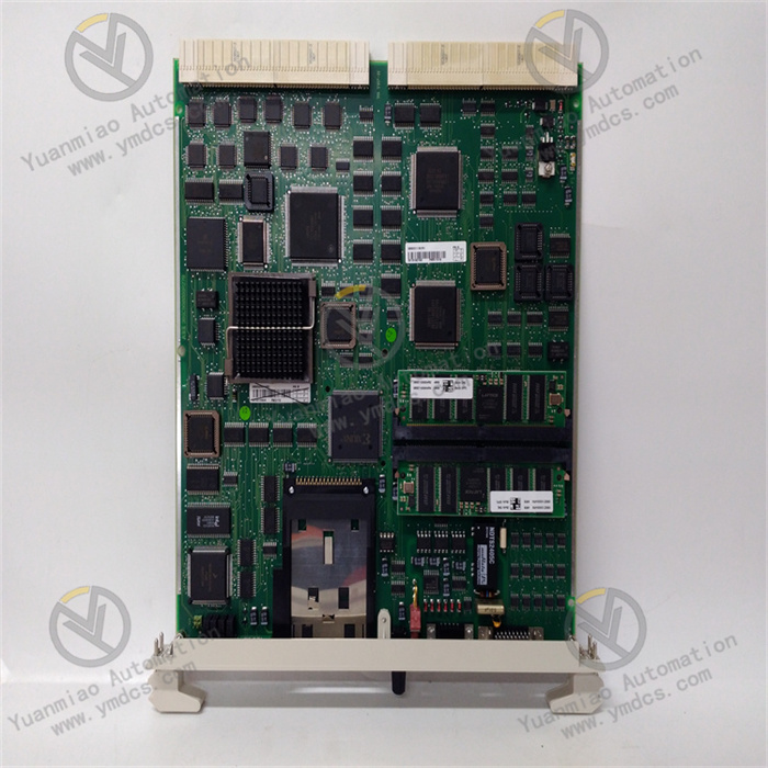
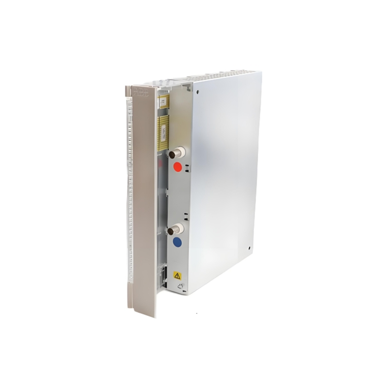
The ABB CI626V1 3BSE012868R1 is an I/O module for the AC 800M controller, belonging to the Communication Interface Module category. It is primarily used in industrial automation systems to enable data interaction between different devices or networks.
Key Functions
Communication Protocol Support
- Supports the PROFIBUS DP V1 protocol, operating as a Master or Slave to connect field devices (such as sensors, actuators, and frequency converters).
- Compatible with high-speed PROFIBUS DP communication (up to 12 Mbps), suitable for industrial control scenarios requiring real-time performance.
Data Interaction Capability
- Handles input/output data (e.g., process variables, status signals) and supports both periodic data transmission (cyclic communication) and aperiodic data transmission (e.g., parameter settings, diagnostic information).
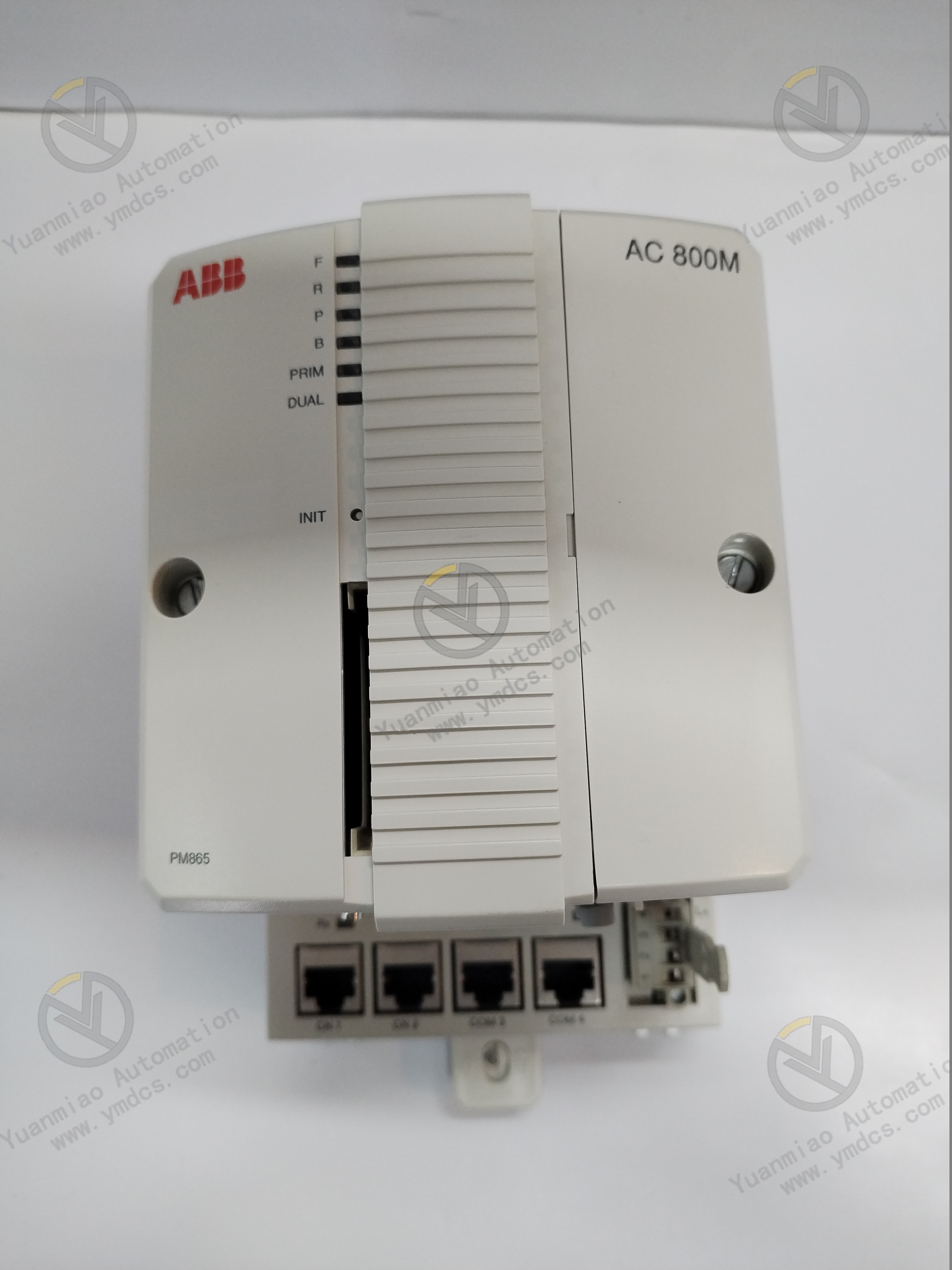
- Enables seamless integration with ABB AC 800M controllers to achieve centralized monitoring and management in distributed control systems (DCS).
Diagnosis and Redundancy
- Features self-diagnosis functionality to real-time monitor communication link status and module faults (e.g., power anomalies, bus disconnections), with alarms indicated via LED indicators or system software.
- Supports redundant configuration (requires redundant power supplies and bus architecture) to enhance system reliability and reduce downtime risks.
Technical Parameters
| Parameter | Details |
|---|---|
| Model | CI626V1 3BSE012868R1 |
| Series | AC 800M I/O Module |
| Communication Protocol | PROFIBUS DP V1 (Master/Slave) |
| Transmission Rate | 9.6 kbps ~ 12 Mbps (auto-negotiation) |
| Maximum Number of Slaves | 126 (depending on bus load and transmission rate) |
| Data Capacity | - Input: Up to 244 bytes - Output: Up to 244 bytes |
| Power Supply Voltage | 24 V DC (from system backplane) |
| Power Consumption | Approximately 2.5 W |
| Operating Temperature | -40°C ~ +70°C (non-condensing) |
| Protection Class | IP20 (requires installation in a control cabinet) |
| Mounting Method | Rail mounting (with AC 800M controller rack) |
| Diagnostic Functions | Module status indicators (power, communication, fault), bus fault detection |
| Redundancy Support | Hardware redundancy supported (requires redundant modules and buses) |
Physical Characteristics
Appearance and Interfaces
- Module Dimensions: Approximately 36 mm (width) × 175 mm (height) × 150 mm (depth) (subject to the manual for specifics).
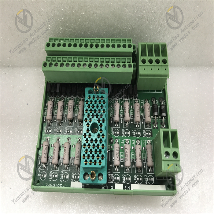
- Interface Types:
- PROFIBUS Interface: Connects to bus cables via a Sub-D 9-pin connector.
- Backplane Interface: Connects to the AC 800M controller rack’s backplane bus via metal contacts for power and data transmission.
LED Indicators
- PWR (Power): Green light indicates normal power supply.
- BUS (Bus Status): Flashing green light indicates active communication; off light indicates bus disconnection or fault.
- FAULT (Fault): Red light indicates module fault or communication anomaly.
Application Scenarios
- Industrial Automation Systems: Used in production line control for industries such as chemical, power, metallurgy, and pharmaceuticals to connect field devices and control systems.
- Distributed Control Systems (DCS): Serves as a core node in PROFIBUS networks to enable data interaction between controllers and remote I/O stations or intelligent devices.
- Process Control and Monitoring: Supports real-time data acquisition and command issuance, suitable for scenarios requiring high-speed communication and reliability.
Installation and Wiring
Installation Steps
- Insert the module into the corresponding slot of the AC 800M controller rack (operate with power off).
- Secure the module with rail clips to ensure good contact.
- Connect the PROFIBUS bus cable: Master stations require terminal resistors (typically 120 Ω) at both ends of the bus; slave stations do not.
Wiring Considerations
- Use shielded twisted-pair cables for PROFIBUS to minimize electromagnetic interference (EMI).
- Ensure the bus positive/negative poles (red for +, black for -) match the module’s interface definitions (refer to the manual’s pin diagram).
- If configuring redundant modules, connect redundant bus cables and set corresponding hardware addresses.
Configuration and Programming
- Hardware Configuration: Define parameters such as module type, bus address (e.g., PROFIBUS slave addresses 1–126), and input/output data length via ABB Control Builder M software.
- Programming Interface: Use standard PROFIBUS communication function blocks (e.g., read input data, write output data) in PLC programs to interact with field devices.
Maintenance and Fault Handling
Daily Maintenance
- Regularly check the module’s indicator lights to ensure normal power supply and communication.
- Clean dust from the module surface to avoid poor heat dissipation (recommended every 6–12 months).
Common Faults and Solutions
| Fault Phenomenon | Possible Cause | Solution |
|---|---|---|
| BUS light off | Bus disconnection, missing terminal resistor | Check cable connections and install terminal resistors. |
| FAULT light on | Module fault, address conflict | Restart the module and check bus address uniqueness. |
| Abnormal data communication | Electromagnetic interference, baud rate mismatch | Replace with shielded cables and reconfigure baud rates. |
| Module overheating | High ambient temperature, poor heat dissipation | Improve ventilation and clean the heat sink. |