Description
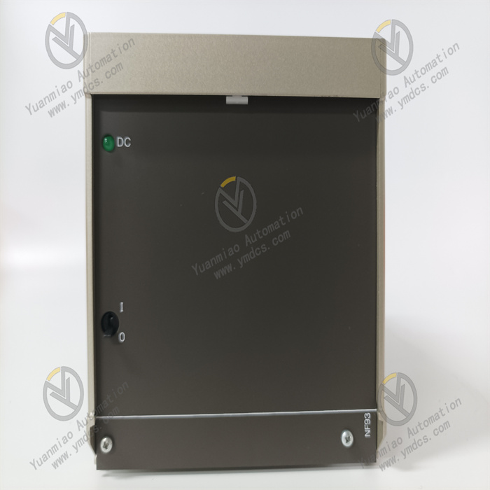
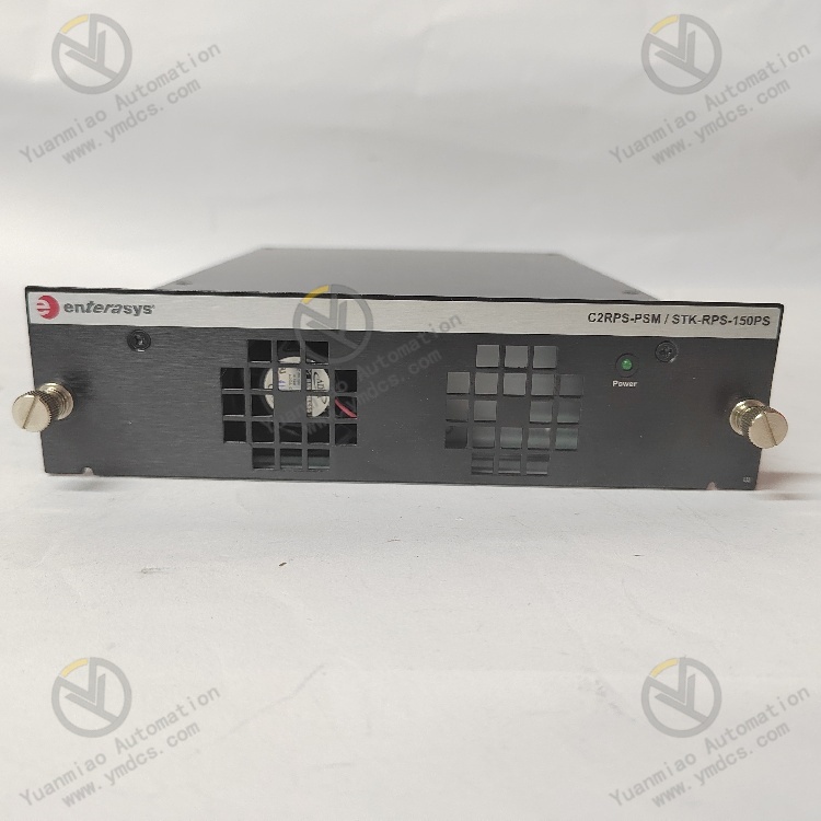
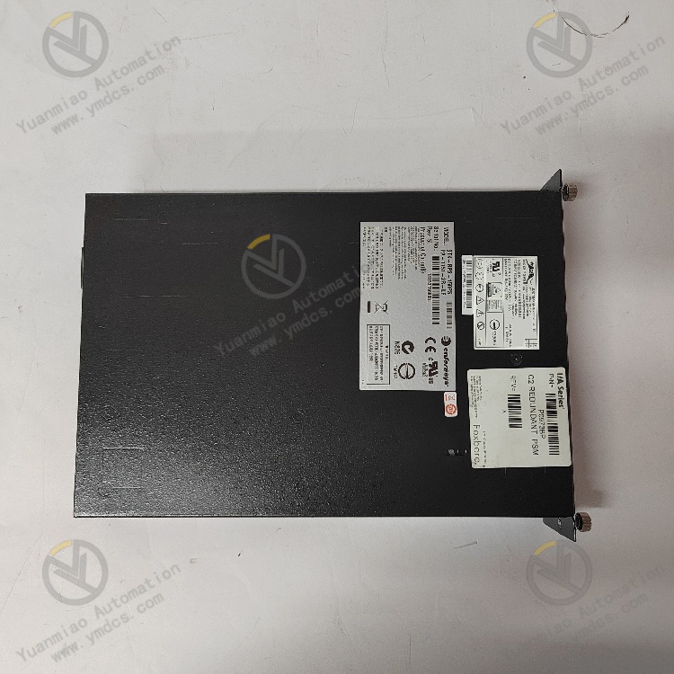
Enterasys STK-RPS-150PS P0973BP
Functional Features
- High-Reliability Redundant Power Supply Design
- Hot-Swap Redundant Power Supply: Supports parallel redundant configuration with the same model power modules, ensuring the system continues to operate in the event of a single power failure and reducing downtime risks.
- Automatic Fault Switching: Built-in intelligent management circuitry enables seamless switching to the redundant power supply when the main power fails, ensuring stable power supply to equipment.
- Efficient Power Output and Compatibility
- Rated Power: Provides a stable 150W output power, suitable for power supply requirements of small and medium-sized network devices (such as switches and routers).
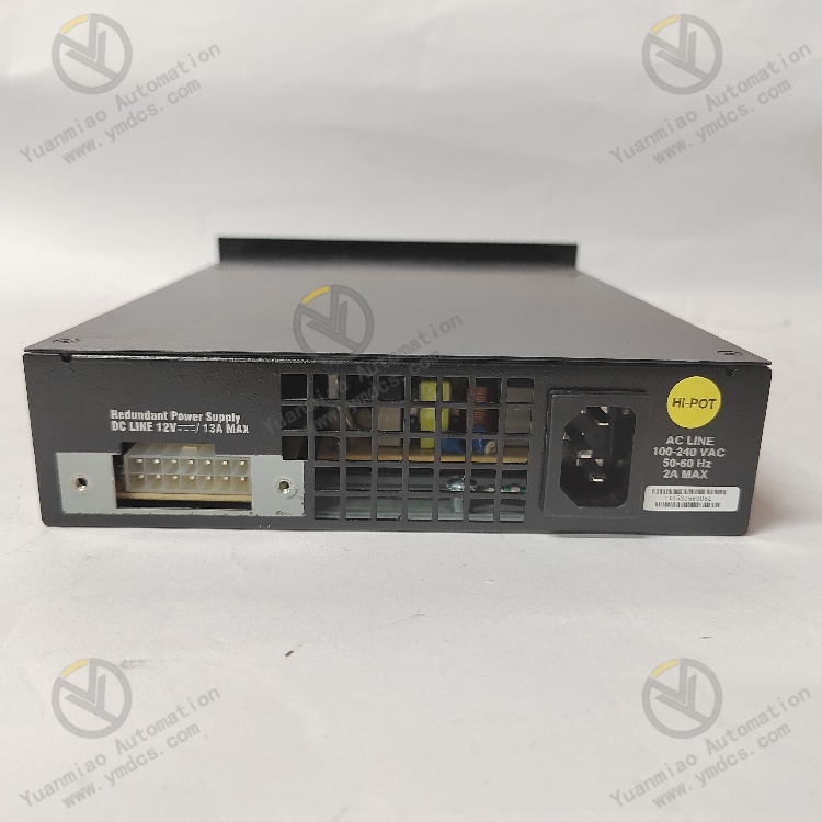
- Wide Voltage Input Range: Supports full voltage input of 100-240V AC, compatible with power grids in different regions worldwide, offering strong adaptability.
- Complete Safety Protection Mechanisms
- Overload Protection: Automatically limits output or cuts off power when the load exceeds the rated power to prevent equipment damage.
- Short Circuit Protection: Rapidly cuts off power when a short circuit is detected at the output terminal to prevent circuit burnout.
- Overvoltage/Undervoltage Protection: Monitors input voltage in real time to ensure the output voltage remains within a safe range.
- Multiple Electrical Protections:
- Temperature Monitoring and Cooling: Built-in temperature-controlled fans automatically adjust the cooling intensity according to internal temperature to avoid failures caused by overheating.
- Intelligent Management and Status Monitoring
- Status Indicator Lights: Equipped with intuitive LED indicators to display real-time power supply status (such as normal operation, fault, redundant mode, etc.), facilitating quick problem troubleshooting.
- Remote Monitoring Interface (Partial Models): Supports monitoring of power supply status through device management systems (such as the switch's Web interface) to enable remote operation and maintenance.
- Industrial-Grade Durability and Certification
- High-Reliability Design: Uses high-quality electronic components and undergoes rigorous aging tests, suitable for long-term continuous operation to meet the needs of industrial-grade or enterprise-level network environments.
- Compliance Certifications: Meets international safety standards such as UL, CE, and FCC to ensure electromagnetic compatibility (EMC) and safety performance.
- Easy Installation and Maintenance
- Plug-and-Play Design: Supports rail mounting or rack mounting, compatible with standard network equipment cabinets, and features a simple and quick installation process.
- Tool-Free Maintenance: The hot-swap design allows replacement of faulty power modules without shutting down the system, reducing maintenance complexity.
Technical Parameters
- Input Parameters
- Input Voltage Range: 100-240VAC, adapting to power standards in different regions.
- Output Parameters
- Output Voltage: Stable 12V DC output.
- Maximum Output Power: 150W, meeting the power requirements of switches.
- Other Parameters
- Hot-Swap Function: Supports hot swapping, allowing replacement or addition of power modules while the switch is running.
- Status Indication: Front-panel LED indicators display the working status of the power module.
- Compatibility: Compatible with various A4 series and/or C series managed switches, such as 24-port copper, 24-port fiber, or 8-port copper/8-port fiber switches.
Operation Guide for Enterasys STK-RPS-150PS P0973BP
Installation
- Installation Preparation: Confirm that the switch model to be installed is compatible with the STK-RPS-150PS P0973BP, and prepare installation tools such as a screwdriver.
- Installation Method Selection: The power module can be installed as a standalone unit or in a RPS rack with two or eight slots, which is then installed in a standard 19-inch rack.
- Specific Installation Steps:
- For installation in a RPS rack: First secure the RPS rack to the equipment rack, then insert the power module into the corresponding slot of the RPS rack.
- For standalone installation: Choose a suitable location to ensure sufficient space for heat dissipation and maintenance, and secure it firmly with screws, etc. Ensure the module is stable and the interface direction is correct during installation.
- Power and Switch Connection: Connect the module's input power cord to a suitable AC power outlet, ensuring the input voltage is within the 100-240VAC range. Then connect the power module to the switch via a modular slot, ensuring a secure connection to avoid looseness.
Configuration
This power module typically requires no complex configuration to function properly. However, if the switch supports relevant power management functions, you may need to make settings through the switch's configuration interface, such as:
- Redundancy Mode Settings: Set the working mode between the power module and the switch's internal power supply or other redundant power supplies (such as load sharing, backup, etc.) according to actual needs.
- Alarm Settings: Configure how alarm signals are issued (such as email notifications, SNMP traps, etc.) when the power module fails or malfunctions.
Daily Operation
- Status Check: View the working status of the power module through the front-panel LED indicators. A steady green light indicates that the AC input power is within specifications and the power supply is operating normally; if the light is off, it indicates that the AC input power is outside the specifications, requiring inspection of the AC power cord connection, power outlet, and attempted replacement of the power cord.
- System Monitoring: If the switch supports relevant functions, you can remotely monitor the power module's status (such as output voltage, current, and fault alarms) through the switch's management interface or network management system.
Maintenance and Troubleshooting
- Regular Maintenance: Regularly inspect the appearance of the power module to ensure there is no dust accumulation, physical damage, or overheating. Clean the module's surface and cooling channels to maintain good heat dissipation performance. Additionally, check for loose connection cables and tighten them promptly if found.
- Fault Troubleshooting: If a power module fault is detected (such as abnormal LED indicators or the switch reporting a power fault), first refer to the fault codes and solutions in the manual for troubleshooting. Common causes include power input issues, connection faults, or module itself failures. For power input issues, check the AC power cord and outlet; for connection faults, recheck the connection between the module and the switch; if a module failure is suspected, try replacing it with a new power module and contact a professional technician for repair or further inspection.
- Hot-Swap Replacement: Since the module supports hot swapping, it can be replaced while the switch is running when needed. First, turn off the input power of the module to be replaced, carefully remove it from the slot, insert the new module, and then turn on the input power. Note that correct operation methods must be followed when plugging and unplugging the module to avoid issues caused by improper handling.