Description
GE Multilin SR465-P5-HI-A20
I. Overview
The GE Multilin SR465-P5-HI-A20 is a high-performance motor management relay meticulously designed for industrial applications. Belonging to GE Multilin's product portfolio, it sets a benchmark in motor protection and precise control with the series' shared excellent design features and compatibility. This relay provides comprehensive protection and monitoring for the operational status of medium to large motors, widely applied in key industrial fields such as industrial automation production lines, power supply systems, pumping station power equipment, fan drive units, conveyor systems, machine tool control units, and compressor power modules. It has become a core device to ensure the safe, stable, and efficient operation of various motors.
II. Functional Features
All-Round Precision Protection Mechanism
Equipped with rich and practical protection functions, it defends against motor operation risks without blind spots:
- Overload Protection acts as a vigilant guard, constantly monitoring the motor's load status. When detecting prolonged overloading, it swiftly takes action via preset protection strategies to prevent damage from continuous overheating.
- Short-Circuit Protection responds as rapidly as lightning, immediately cutting off the circuit during sudden large currents caused by short circuits to prevent irreversible damage to the motor and related equipment.
- Undervoltage Protection effectively addresses insufficient supply voltage, preventing the motor from malfunctioning due to low voltage or even burning out from stalling.
- Phase Sequence Protection accurately identifies correct power phase sequences. Upon detecting abnormalities, it immediately prevents motor reverse rotation to avoid equipment failures and safety accidents.
- Additional functions like overvoltage protection and temperature protection may also be integrated, constructing an impregnable safety barrier for smooth motor operation.
High-Precision Parameter Measurement Capability
It accurately captures key motor operation parameters such as current, voltage, frequency, and power. These high-precision measurements provide reliable and precise data support for technicians to quickly and accurately assess the motor's operational health, whether for real-time status monitoring or in-depth fault troubleshooting and analysis.
Intelligent Thermal Capacity Regulation System
Supporting advanced thermal capacity management, it excels in handling unbalanced bias issues during motor operation. Through real-time and precise monitoring and in-depth analysis of the motor's thermal status, it intelligently adjusts operational parameters to effectively avoid motor failures caused by thermal accumulation or load imbalance, significantly extending the motor's service life and reducing equipment replacement and maintenance costs.
Convenient and Flexible Communication Adaptation Scheme
Excellent in communication, it supports common protocols like RS232, RS485, and Ethernet, and perfectly complies with mainstream communication standards such as Modbus, Profibus, and IEC 61850. This feature enables it to seamlessly integrate into various complex automation system architectures. Through these communication interfaces, efficient remote data transmission, real-time motor status monitoring, and precise remote control can be smoothly achieved. Maintenance personnel can grasp the motor's operation status anytime, anywhere via connected system terminals, promptly detecting and addressing potential fault risks.
Simple and User-Friendly Operation Interface
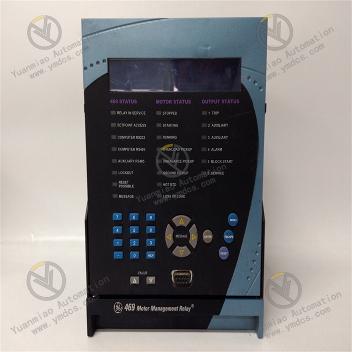
Adopting an optimized enhanced front-panel design with a specially sealed pull-out handle, this design not only greatly facilitates equipment installation and daily maintenance but also effectively prevents equipment failures or safety accidents caused by misoperations. The front panel is reasonably arranged with clear LED indicators for intuitive display of key device status information, a 40-character LCD screen for detailed presentation of motor operation parameters, fault alarm information, and protection function activation status, as well as dedicated communication ports and operation buttons. Operators can easily complete tasks like motor parameter setting and function option switching through simple button operations combined with screen prompts.
Exceptional Reliability and Durability
Manufactured with high-quality raw materials and advanced manufacturing processes, the product is endowed with extremely high reliability and durability. Some models feature special optimized designs for harsh industrial environments, such as protective coatings on the housing surface, enabling effective resistance to corrosion, hydrogen sulfide, and adverse effects of high humidity. Even in complex and severe industrial environments, it maintains stable operation, significantly reducing equipment failure rates and overall maintenance costs.
III. Technical Parameters
- Rated Voltage: With excellent power adaptability, it supports 90-300 VDC DC control power input and 70-265 VAC AC control power input, seamlessly adapting to power supply requirements of different power systems to ensure stable operation in various power environments.
- Rated Current: Available in specifications like 5A or 1A, it allows flexible selection of matching rated current specifications based on the motor's load current in practical applications, ensuring accurate acquisition and processing of motor current signals.
- Phase CT Secondary Coil: Commonly configured as 5A, this specification is designed for precise acquisition of current signals from each motor phase, providing a reliable data foundation for internal protection algorithms and parameter calculations.
- Input Ports: Equipped with 5 analog and digital input ports, the rich input interfaces facilitate convenient access to various sensors and control signal sources, enabling comprehensive perception and reception of the motor's operating environment and control commands.
- Output Ports: Features 2 analog output ports with a standard output signal of 4-20mA, which can be easily connected to external devices such as data acquisition modules and regulating actuators in automation control systems for remote signal transmission and precise control.
- Maximum Load Current: Up to 2A, this indicator means the device has certain load driving capabilities to meet the requirements of some application scenarios with high output load demands.
- Operating Frequency: The operating frequency range is set at 48-62Hz, covering power frequency standards in most regions worldwide, giving the product broad geographical applicability and enabling stable operation in power system environments of different countries and regions.
- Protection Level: Some models reach IP54, with good dustproof and water splash resistance, suitable for harsh industrial outdoor environments or dusty and humid indoor working environments; others with IP20 are mainly suitable for motor management and protection in general indoor clean environments.
- Communication Interfaces: Supports multiple communication interface types such as RS232 (baud rate programmable up to 19200), RS485, and Ethernet. Diverse communication interface options provide great convenience for data interaction between the device and host computers, other intelligent devices, or automation systems, meeting connection needs of different users under various communication architectures.
- Operating Temperature: The general operating temperature range is -20°C to 60°C, adapting to temperature changes in most conventional industrial environments. Partially specially designed and optimized products have an extended operating temperature range to -40°C to +85°C, capable of normal operation in extremely cold or hot special environments, demonstrating strong environmental adaptability.
- Humidity: It can adapt to non-condensing environments with relative humidity up to 90%, ensuring stable operation in humid environments such as coastal industrial facilities and wet workshops, and avoiding electrical performance degradation or equipment failures due to humidity.
- Dimensions: The product dimensions are approximately 200mm x 165mm x 80mm (specific dimensions may vary slightly depending on the actual product version). The compact and reasonable design allows easy installation and arrangement in electrical control cabinets or equipment integration scenarios with limited installation space.
- Weight: Approximately 2.2 kg, the moderate weight facilitates single-person installation, handling, and maintenance operations, while ensuring the device's stability after installation, making it less prone to displacement or damage due to vibration, external collisions, or other factors.
V. Operation Guide
Local Operation
- Boot and Initialization Process: After the device is powered on, the SR465-P5-HI-A20 relay will automatically start the self-check and initialization program. During this process, the LED indicators on the front panel will flash in a specific order to visually feedback the self-check progress to the operator. At the same time, the 40-character LCD display will simultaneously display detailed self-check information, including the detection results of the device hardware status and software version information. When the self-check process is successfully completed, the LCD display will automatically switch to the interface displaying the real-time operating parameters of the motor, such as the current three-phase current values and three-phase voltage values, so that the operator can master the operating status of the motor at the first time.
- Menu Operation Steps: If the operator needs to perform function settings, parameter adjustments, or information viewing on the device, they can press the eye-catching "Menu" button on the front panel, and the device will enter the main menu interface. The main menu interface is designed to be simple and clear, including several main function options such as "Settings", "Monitoring", and "Fault Records". The operator can quickly switch and select among the menu options by pressing the up and down direction keys on the front panel, and press the "Enter" key to enter the corresponding submenu when the desired function option is selected.
- Parameter Setting Method: In the "Settings" submenu, it is further subdivided into several special setting submenus such as "Motor Parameters", "Protection Settings", and "Communication Settings". For example, in the "Motor Parameters" submenu, the operator can accurately set the key parameters of the motor such as rated power, rated current, and rated voltage according to the specification model of the actually connected motor; in the "Protection Settings" submenu, the important protection parameters such as the action current multiple and action time delay of the overload protection function, and the action current threshold of the short-circuit protection function can be flexibly adjusted. When entering the parameter values, use the specially equipped digital keys on the front panel to operate, and after the input is completed, press the "Enter" key again, and the device will automatically save and confirm the set parameter values.
- Application of Monitoring Function: After entering the "Monitoring" menu, the operator can view multiple operating parameters of the motor in real time, including the real-time values of three-phase current, three-phase voltage, the current output power of the motor, and operating frequency and other key information. At the same time, the menu interface will also intuitively display the real-time operating status of the motor, such as whether the motor is in the running, stopped, or fault alarm state, etc., so that the operator can grasp the working conditions of the motor at any time and find potential problems in time.
- Method for Viewing Fault Records: When a fault occurs during the operation of the motor, the SR465-P5-HI-A20 device will automatically and timely record detailed fault information. The operator can view the specific type of fault, such as overload fault, short-circuit fault, undervoltage fault, etc.; the accurate time of the fault, accurate to the second level; and the values of various operating parameters of the motor at the moment of the fault, such as the current, voltage, power, etc., by entering the "Fault Records" menu. These detailed fault record information provide crucial clues for subsequent fault troubleshooting and analysis, helping technicians quickly locate the cause of the fault and formulate effective solutions.
- Method for Exiting the Operation: When the operator has completed all local operation tasks, they can press the "Exit" key on the front panel, and the device will gradually return to the upper-level menu interface. Continue to press the "Exit" key until the menu operation interface is completely exited and return to the main interface displaying the real-time operating parameters of the motor, at which time the device will continue to maintain the real-time monitoring and protection function of the motor's operating status.
Remote Operation
- Establishment of Communication Connection: Before performing remote operations, the primary task is to ensure that the communication line connection between the SR465-P5-HI-A20 device and the external automation system is accurate, and the communication parameter settings of both parties are completely consistent. Common communication connection methods include RS485 serial communication, Ethernet communication, etc. Taking RS485 communication as an example, it is necessary to carefully check whether the wiring polarity of the communication cable is correct to ensure a stable and reliable physical connection between the device and the automation system. At the same time, according to the actual connection situation, accurately set the corresponding communication parameters in the "Communication Settings" menu of the device and the communication parameter configuration interface of the automation system, such as the baud rate (which can be set according to actual needs, up to 19200), the communication address (used to uniquely identify the position of the device in the communication network), etc.
- Operation Process of Monitoring Software: After completing the communication connection and parameter setting, the operator needs to open the host computer monitoring software. In the device management interface of the monitoring software, find the device icon corresponding to the SR465-P5-HI-A20. The communication connection between the monitoring software and the device can be attempted by double-clicking the icon or by first selecting the device icon and then clicking the "Connect" button on the software interface. Once the connection is successful, the monitoring software interface will display various operating parameters, status information, etc. of the motor in real time, and the displayed content is basically the same as the information presented by the "Monitoring" function in the local operation interface of the device, which is convenient for remote operators to understand the operating situation of the motor in real time.
- Operation of Remote Parameter Setting: In the monitoring software, there is a special parameter setting interface for the SR465-P5-HI-A20 device. In this interface, the operator can perform remote setting operations on motor parameters, protection parameters, communication parameters, etc. The operation method is similar to the local menu setting method of the device. For example, when setting the motor rated current parameter, enter the accurate value in the corresponding parameter input box in the software interface, and then click the "Save" or "Apply" button to send the set parameter value to the device end. However, when performing remote parameter setting operations, the issue of operation authority management must be highly valued. Only personnel with corresponding operation authority can perform parameter modification operations to ensure the safety and accuracy of the entire system operation and avoid equipment failures or production accidents caused by misoperations.
- Key Points of Remote Control Operation: Some monitoring software with perfect functions also supports remote control operations on the motor, such as remotely starting the motor, stopping the motor operation, and controlling the forward and reverse rotation of the motor. In the monitoring software interface, there is usually a special motor control button area. The operator only needs to click the corresponding control button, such as the "Start" button, "Stop" button, "Forward" button, or "Reverse" button, etc., and the monitoring software will send the corresponding control command to the SR465-P5-HI-A20 device according to the preset communication protocol. After the device receives the control command, it will quickly execute the corresponding control action to achieve the remote control of the motor. However, during the remote control operation process, the operator must always pay attention to the actual operation status of the on-site equipment and the safety of the surrounding personnel to ensure the safety and reliability of the remote control operation and prevent equipment damage or personal injury and other accidents caused by improper remote control.


