Description
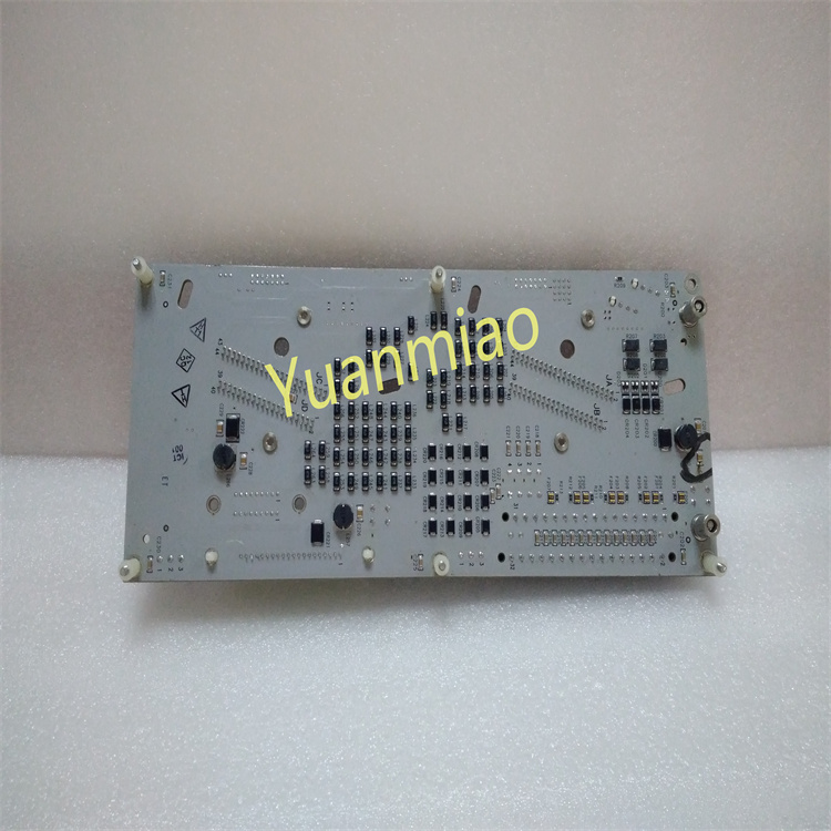
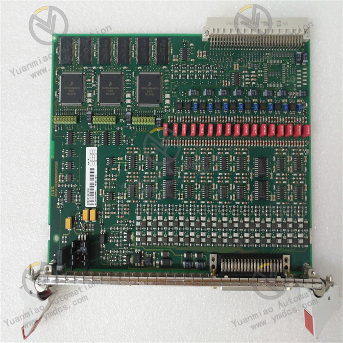
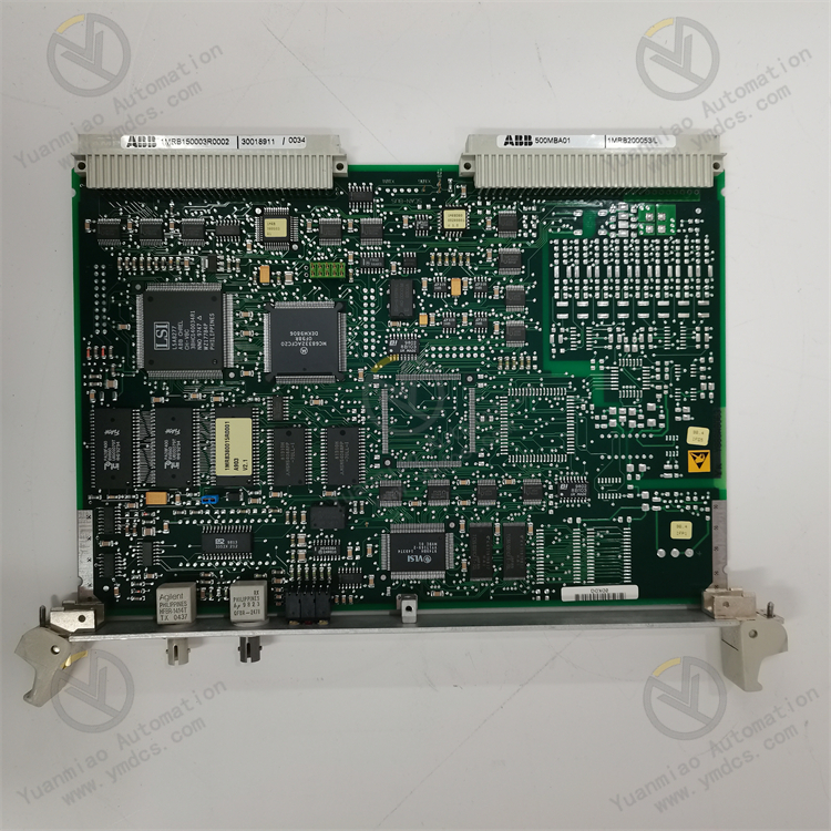
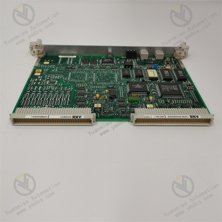
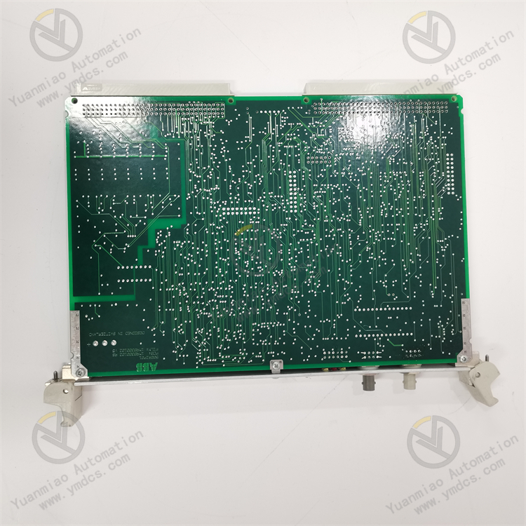
ABB 500MBA01 1MRB150003R0002 1MRB200053/L
500MBA01 Control Card (1MRB150003R0002)
Main Features:- Modular Design: Easy to integrate and maintain, adapting to various industrial application requirements.
- High Reliability: Uses industrial-grade components to ensure long-term stable operation.
- Multifunctionality: Supports multiple input/output configurations to meet complex control requirements.
Technical Specifications:
- Input Voltage: 24V DC
- Digital Input/Output: 8 DI / 8 DO
- Analog Input/Output: 4 AI / 2 AO
- Communication Interfaces: RS-485, Ethernet
- Operating Temperature: -20°C to +60°C
Application Scenarios:
- Process control in industries such as chemical engineering and oil & gas automation.
- Production line automation in manufacturing and power system monitoring & control in energy management.
1MRB200053-L Control Card
Main Features:- High-Performance Processing: Suitable for complex control tasks.
- Flexible Communication Options: Supports multiple industrial protocols for easy system integration.
- Robust Design: Complies with industrial standards and adapts to harsh environments.
Technical Specifications:
- Input Voltage: 24V DC
- Digital Input/Output: 16 DI / 16 DO
- Analog Input/Output: 8 AI / 4 AO
- Communication Interfaces: PROFIBUS, Modbus
- Operating Temperature: -20°C to +70°C
Application Scenarios:
- Building automation control in building management systems.
- Monitoring and control of water treatment processes.
General Operation Guide
Preparations
- Hardware Inspection: Ensure the control card has no physical damage and all interfaces are secure. Check connections to all devices (e.g., sensors, actuators) for firm attachment.
- Technical Specifications Review: Familiarize with parameters such as input voltage (24V DC), I/O counts (8 DI/8 DO for 500MBA01; 16 DI/16 DO for 1MRB200053-L), analog I/O counts (4 AI/2 AO for 500MBA01; 8 AI/4 AO for 1MRB200053-L), and communication interfaces (RS-485/Ethernet for 500MBA01; PROFIBUS/Modbus for 1MRB200053-L).
- Software and Tools Preparation: Ready corresponding configuration software and programming tools based on the control card’s interfaces and functions. Ensure the computer can communicate with the control card.
Installation and Connection
- Control Card Installation: Mount the card in an industrial control cabinet with good ventilation, away from high temperatures, humidity, and strong electromagnetic interference. Secure it firmly using screws or rail mounting.
- Power Connection: Connect a 24V DC power supply to the card’s input, ensuring correct polarity and stable power.
- I/O Device Connection:
- Connect digital inputs (e.g., buttons, switches) to DI ports and digital outputs (e.g., relays, indicators) to DO ports per the wiring diagram.
- For analog inputs (e.g., sensors), use shielded cables to connect to AI ports and reduce interference. Connect analog outputs to actuators (e.g., control valves, variable frequency drives).
- Communication Network Connection:
- For RS-485: Properly connect A/B signal lines, set unique device addresses, and ensure no conflicts.
- For Ethernet: Connect to a switch and configure IP address settings.
- For PROFIBUS/Modbus: Follow protocol specifications for connection and parameter setup.
Parameter Configuration
- Software Launch: Start the configuration software and establish a connection with the control card via the communication interface.
- Basic Parameter Setup: Configure device name, communication parameters (baud rate, data bits, stop bits), and I/O signal types/ranges. Set digital I/O logic states (e.g., high/low active) and analog I/O ranges (e.g., 0-10V, 4-20mA).
- Control Function Configuration: Set control algorithm parameters (e.g., PID), alarm thresholds, and timer/counter values based on specific tasks. For temperature control, configure setpoints, alarm limits, and PID coefficients (P, I, D).
- Parameter Save and Download: Save configurations to the computer and download them to the control card to take effect.
Operation and Monitoring
- Startup: Power on the control card after confirming parameter configuration. The card will load parameters and start the control program.
- I/O Status Monitoring: Use software or tools to real-time monitor DI/DO states and AI/AO values. Verify that inputs reflect field devices and outputs control actuators as expected.
- Control Process Monitoring: Observe whether the controlled object (e.g., temperature, flow) meets the set target. Adjust control parameters promptly if performance is unsatisfactory.
- Alarm Handling: Respond to alarm signals by checking alarm details, identifying causes, and taking corrective actions (e.g., inspecting faulty heating equipment or sensors for over-temperature alarms).
How to Diagnose and Troubleshoot ABB 500MBA01 Control Card Faults?
I. Hardware Fault Diagnosis and Elimination
- Power Supply Faults
- Phenomenon: No indicator lights or frequent restarts.
- Troubleshooting Steps:
- Measure the input voltage with a multimeter to ensure it is stable 24V DC (±10% tolerance).
- Check power connections for looseness, short circuits, or poor contact; replace cables or the power module for testing.
- If power is normal but the card is unresponsive, the internal power module may be damaged—contact ABB for replacement.
- Abnormal Indicator Lights
- Common Indicator Meanings (model-specific details refer to the manual):
Indicator Color/State Description PWR Green (steady) Normal power supply Off No power input or power failure RUN Green (flashing) Normal operation Off Unstarted or program error ERR Red (steady) Hardware fault (e.g., memory, chip) COM Green (flashing) Normal communication (Ethernet/RS-485) Off/Steady Communication failure or misconfiguration - Solutions:
- PWR off: Prioritize power supply and wiring checks (see "Power Supply Faults").
- RUN off/steady: Reboot the card; if failed, reflash firmware via official software (exercise caution to avoid bricking).
- ERR on: Hardware damage (e.g., motherboard, interface chip)—contact technical support or replace spare parts.
- COM abnormal: Check cable connections, reconfigure communication parameters (IP address, baud rate), or replace the communication module.
- Input/Output (I/O) Faults
- Phenomenon:
- DI: No feedback when field switches act (e.g., DI indicator off).
- DO: No actuator response after command (e.g., relay not engaged, indicator off).
- AI/AO: Abnormal readings (e.g., fixed values, fluctuations) or no output.
- Troubleshooting Steps:
DI Faults:
- Verify input type (dry/wet contact) matches software configuration (active/passive input).
- Measure terminal voltage with a multimeter to ensure signal transmission (dry contact should conduct; wet contact should meet voltage range).
- Switch to a spare DI channel to identify channel vs. external device issues.
- DO Faults:
- Check output type (relay/transistor) for compatibility with the actuator power supply to avoid overload.
- Light on but no action: Check wiring, actuator power, or output module damage.
- Light off: Program logic error or channel failure—reboot or switch channels.
- AI/AO Faults:
- Confirm analog signal type (4-20mA, 0-10V) matches the card’s configured range.
- Compare AI terminal measurements with card readings:
- Large discrepancies: Check grounding, shielded cables, or sensor faults.
- No signal: Inspect sensor power, wiring, or AI channel damage.
- For AO, send a fixed signal (e.g., 5V, 10mA) and measure the terminal:
- No output: AO module fault or parameter activation issue (check "enable output").
- Abnormal output: Actuator overload or cable short/break.
II. Software and Configuration Fault Diagnosis
- Communication Connection Failure
- Phenomenon: Software cannot recognize the card or communication is intermittent.
- Troubleshooting Steps:
- Ensure matching communication interface types and parameters:
- Ethernet: Verify IP address compatibility (e.g., default 192.168.1.100) and ping connectivity.
- RS-485/Modbus: Check baud rate, parity, and terminal resistance (e.g., 120Ω); ensure unique device addresses (0-247).
- Replace cables or interface modules to rule out physical layer issues.
- Temporarily disable firewalls/antivirus software interfering with communication.
- Parameter Configuration Errors
- Phenomenon: Abnormal functions (e.g., PID oscillation, false alarms).
- Troubleshooting Steps:
- Restore factory settings and reconfigure key parameters (I/O types, communication, PID).
- Validate parameter ranges in the manual (e.g., AI range set to 4-20mA instead of 0-20mA; DI mode set to sinking/sourcing as needed).
- For PID control, check SP, P/I/D values and start with default parameters for optimization.
- Program Logic Errors
- Phenomenon: Unintended I/O actions or chaotic control flows.
- Troubleshooting Steps:
- Use software’s online monitoring to track variable states and program execution for logic errors.
- Test program segments incrementally (e.g., DI triggering DO) to isolate conflicts in complex logic.
- Check for undefined variables or unreasonable timeout settings (e.g., excessive timer values).
III. System-Level Fault Troubleshooting
- Electromagnetic Interference (EMI)
- Phenomenon: Fluctuating analog signals, false digital triggers, or communication interruptions.
- Solutions:
- Separate power and signal cables by ≥30cm to avoid parallel routing.
- Use shielded twisted-pair cables for analog signals, grounding the shield at the control card end.
- Ensure proper grounding (resistance <10Ω) for the card and cabinet; add EMC filters if necessary.
- Compatibility Issues
- Phenomenon: Communication failures with third-party devices (e.g., VFDs, PLCs) or mismatched I/O signals.
- Solutions:
- Confirm protocol compatibility (e.g., Modbus RTU/ASCII, PROFIBUS DP) and data frame formats (register addresses, read/write permissions).
- Test third-party devices standalone to rule out protocol conversion or firmware compatibility issues.
- Update the control card firmware or third-party device drivers to the latest versions.