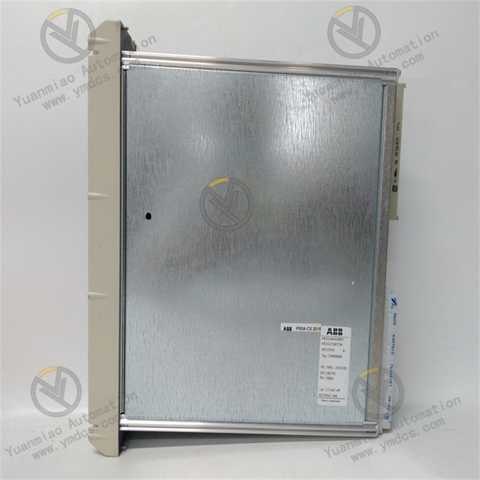
Description
GE IC693DNM200-BD
I. Overview
II. Technical Parameters
Power Requirements: The input voltage is 5V DC, provided by the backplane of the RX3i system it belongs to, without the need for additional power wiring, simplifying the installation and wiring process of the device. Its typical operating current is 120mA, with low power consumption, which will not cause excessive pressure on the overall power load of the system.
Dimensions: Adopting a compact modular design, with a width of 32mm, a height of 110mm, and a depth of 125mm. It can be flexibly installed on the rack of the RX3i series, saving installation space and suitable for use in industrial control cabinets with limited space.
Compatibility: It is compatible with various processor modules (such as IC698CPE020, etc.) and I/O modules of the GE PACSystems RX3i series, and can be seamlessly integrated into the RX3i system without complex compatibility configuration, reducing the difficulty of system integration.
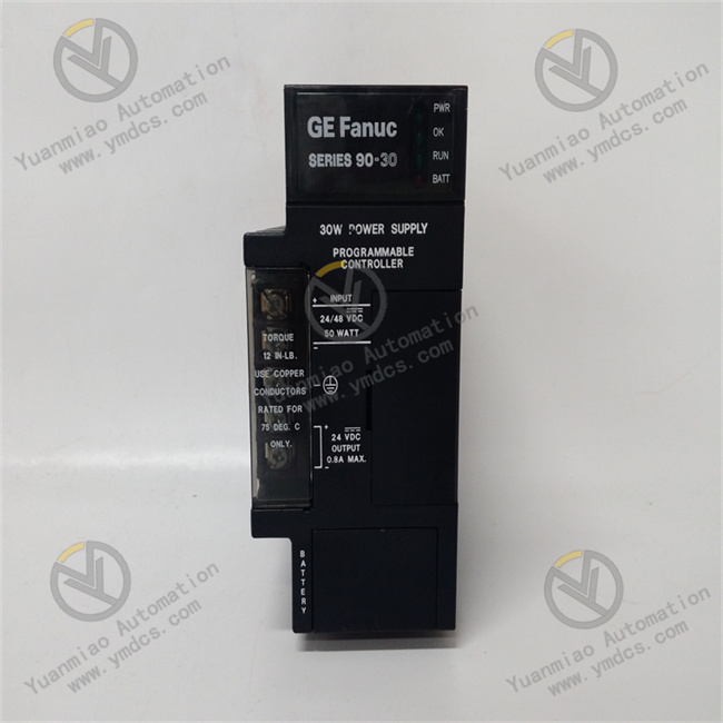
III. Functional Features
Strong Protocol Compatibility: In addition to supporting TCP/IP and Modbus/TCP protocols, it can support the conversion of other industrial protocols through configuration, enabling communication with industrial equipment of different brands and types. For example, it can exchange data with intelligent instruments and sensors using the Modbus/TCP protocol, and also achieve data sharing with upper computer monitoring systems following the TCP/IP protocol, enhancing the flexibility and compatibility of the system.
Stable and Reliable Communication: Using industrial-grade components and design processes, it has strong anti-electromagnetic interference ability, which can effectively resist electromagnetic interference in industrial sites and ensure the accuracy and integrity of data transmission. At the same time, its built-in communication error detection and retransmission mechanism can automatically detect and retransmit when errors occur during data transmission, reducing the probability of data loss and ensuring communication reliability.
Remote Monitoring and Diagnosis: Through the Ethernet interface, remote monitoring and diagnosis of the module itself and the connected devices can be realized. Engineers can remotely view the working status of the module, communication data flow, and error information through upper computer software, timely discover and troubleshoot communication faults, reduce the workload of on-site maintenance, and improve the maintenance efficiency of the system.
IV. Common Faults and Solutions
Possible Causes: Physical damage to the Ethernet interface, such as loose interface, bent or oxidized pins; faults in communication cables, such as broken network cables, poor contact of crystal heads; incorrect network parameter settings, such as IP address conflict with other devices in the network, incorrect subnet mask or gateway settings; faults in network devices (such as switches).
Solutions: Check whether the Ethernet interface is physically damaged. If the interface is loose, re-plug the network cable; if the pins are bent or oxidized, try to repair or replace the module. Replace with a new communication cable and ensure the crystal head is crimped firmly. Check the network parameter settings to ensure that the IP address, subnet mask, and gateway match the network environment and avoid IP address conflicts. Check whether network devices such as switches are working normally, which can be tested by replacing the switch port or the switch.
Possible Causes: Mismatched communication protocols, such as the module using the Modbus/TCP protocol while the other device using another protocol; inconsistent port number settings between devices; firewall or network security settings blocking the communication connection; incorrect communication configuration of the module or the other device.
Solutions: Confirm that the communication protocols used by the module and other devices are consistent. If not, modify the communication protocol of the module through configuration software or perform protocol conversion on the other device. Check and ensure that the port numbers used for communication between devices are the same, such as the default port number of Modbus/TCP is 502. Check the settings of the network firewall or security software and turn off the rules that may block communication. Recheck the communication configuration of the module and the other device, such as device address and data transmission format, to ensure consistent configuration.
Possible Causes: Strong electromagnetic interference in the industrial site, affecting data transmission; excessively long communication cables leading to signal attenuation; reduced anti-interference ability of the module; data transmission rate set too high, exceeding the carrying capacity of the network environment.
Solutions: Take anti-electromagnetic interference measures, such as adding shielding layers to communication cables and keeping cables away from strong electromagnetic interference sources (such as motors, frequency converters, etc.). Shorten the length of communication cables, or use repeaters to enhance signals in long-distance communication. If the anti-interference ability of the module decreases, consider replacing the module. Reduce the data transmission rate to adapt to the network environment and reduce data transmission errors.
Possible Causes: The module is not correctly installed in the rack slot, resulting in poor contact with the backplane; the module itself is faulty, such as internal circuit damage; system power failure, causing the module to be unable to receive power supply; rack or backplane failure, making it impossible to communicate with the module.
Solutions: Reinstall the module into the rack slot to ensure firm installation and good contact with the backplane. Replace with a spare module for testing. If the spare module can be recognized by the system, it indicates that the original module is faulty and needs to be replaced. Check whether the system power output is normal to ensure that the module can receive stable 5V DC power supply. If the rack or backplane is suspected to be faulty, replace the rack or backplane for testing.


